400W Solar Panel,Residential Solar Panel Kits,Solar Panel System,320W Solar Panel Jiangsu Stark New Energy Co.,Ltd , https://www.stark-newenergy.com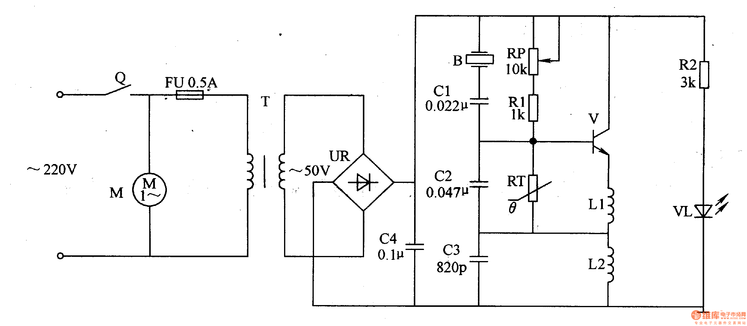
The power circuit is composed of a timer Q, a fuse FU, a power transformer T, a rectifier bridge stack UR, a current limiting resistor R2, a power indicating LED VL, and a filter capacitor C4.
The ultrasonic oscillator circuit is composed of a transistor V, a resistor R1, a potentiometer RP, a thermistor RT, capacitors C2, C3, and inductors L1, L2.
The atomizer circuit is composed of a piezoelectric ultrasonic transducer B, a capacitor C1, and a fan motor M.
Turn on the timer Q, the AC 220V voltage is M power supply, and also provide +5OV working power for the ultrasonic oscillator after T step-down, UR rectification and C4 filtering. The +5OV voltage also illuminates VL after R2 current limit.
The ultrasonic oscillator is oscillated after being energized to generate an ultrasonic oscillation signal having a frequency of 1.65 MHz (B is both a component that determines the frequency of the ultrasonic oscillator and a load of the ultrasonic oscillator). The high-frequency vibration (that is, the ultrasonic directional pressure drop) is generated by the action of the ultrasonic wave, and the chemical liquid is sprayed, and cavitation occurs instantaneously around the sprayed chemical liquid to generate atomization, and the medicine mist is blown out by the fan.
RP is used to adjust the operating current of V, and the operating current of V can be adjusted to about 600mA.
RT is used to stabilize the operating point of the ultrasonic oscillator circuit.
Component selection
Rl selects 2W metal film resistors; cells use 1/4W metal film resistors or carbon film resistors.
The RP uses a small 2W synthetic carbon film potentiometer.
RT uses a 100Ω negative temperature coefficient thermistor.
Cl, C2 and C4 are all selected CBB capacitors with a withstand voltage of 1OOV or higher; C3 is a high frequency ceramic capacitor or mica capacitor.
VL selects high brightness LED of φ5mm.
UR selects 1.5A, lOOV rectifier bridge stack.
V selects BU406 type high back pressure silicon NPN transistor.
L2 uses a 24μH core inductor; Ll uses a φ0.6mm enameled wire to wrap around 5-10 turns on the crucible.
T selects 35-40W, the secondary voltage is 45-55V power transformer.
Q uses a mechanical timer of 0-60min.
M selects AC 220V micro fan.
B selects 1.65MHz finished ultrasonic transducer.