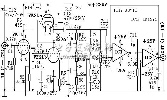
Although the use of electronic tubes in modern electronic technology applications has been less, but because of their superior characteristics that transistors cannot be replaced by transistors, they are also favored in some fields, especially in audio circuits. This is a hybrid amplifier consisting of a "liang" audio tube and a sound integrated circuit. The amplifier is made by the electronic tube as the pre-stage, and the audio special integrated circuits AD711 and LM1875 as the post-stage. The circuit has small distortion, low output impedance, and large dynamic range, which can ensure good sound quality. Due to the combination with the integrated circuit, the circuit is simple. First, the working principle of the circuit The circuit principle is shown in Figure 1. This circuit only draws the left channel part, the right channel is omitted. The circuit selects the double triode 6N2 electron tube to form the line input amplifier (half VE1L of 6N2 is used for the left channel, and the other half VE1R is used for the right channel). R2 is the DC bias resistance of the input stage. When the screen current Iao flows through R2, a DC voltage Eg of about 1.5V is generated, which is added to the gate of VE1L through the gate-drain resistance R1 to form the negative gate voltage of the line amplifier. At this time, VE1L works in Class A state and has good linearity. Another role of R2 is to generate proper AC feedback on the sound source signal, so that the distortion is further reduced and the stability is further improved; the third role of R2 is to form tone feedback. This input stage has outstanding advantages such as high input impedance of hundreds of kiloohms, large dynamic range, and good transient response. This is exactly what the Hi-Fi pre-stage requires. An attenuated tone control network (TCN) is inserted between the front and rear stages. The audio signal output from the VE2La cathode K on the SRPP circuit is sent all the way through the volume potentiometer VR3 to pin 3 of the post-stage integrated circuit IC1; the other is fed to the cathode of the line amplifier VE1L via the TCN network. This combination can effectively suppress dry noise and distortion, while maintaining the adjustment characteristics of the attenuation type TCN. The signal is amplified from VE1L and then output from the anode. It is coupled to the power amplifier exciter VE2 composed of a high-frequency tube 6N3 through a capacitor C2. The two internal transistors are connected in parallel to adjust the push-pull circuit SRPP. The circuit is characterized by low distortion, low output impedance, and large dynamic range, and is fully adapted to various power amplifiers composed of IC, FET, TR, VAL, etc. In Figure (a), capacitors C4 and C5, resistors R7 and R8, and potentiometer VR1 form a bass control network. When VR1 is turned up, the negative feedback of the low-frequency signal from the network composed of C5 and C4 increases, and the bass is relatively weakened. Conversely, when VR1 is turned down, the bass will be relatively enhanced. Capacitors C9, C10, resistors R9, R10 and potentiometer VR2 form a high-tone control network. When VR2 is turned up, the amount of negative feedback of the treble signal increases, and the treble is relatively weakened; conversely, when VR2 is turned down, the treble will be relatively enhanced. In the power amplifier circuit, we hope to get high fidelity and high power output. It is not difficult for general power amplifiers to provide large power to the load, but most of them have the disadvantages of large distortion and poor linearity. If a piece of precision op amp IC1 with good linearity and low distortion is inserted in front of the high-power IC, so that the power amplifier IC2 is in the feedback link of IC1, the effect of gaining strengths and avoiding weaknesses can be achieved. This connection is called "Turbocharged Combination" (TCC). The integrated circuits IC1 (AD711) and IC2 (LM1875) form the post-stage of the TCC power amplifier. In the TCC network, C11, R12, and R13 form an RC network, which provides moderate phase compensation for the audio signal and stabilizes the frequency response area of ​​IC1 and IC2. Figure (b) is the Power Supply circuit diagram of the whole machine. The front-stage high voltage of the electron tube is provided by 280V direct current generated by the rectification of the commercial power. The three filaments of the two electron tubes are connected in series, and the power is supplied by a set of AC 18V to make the circuit simple. Another set of AC 18V generates ± 25V through bridge rectification, C15, C16, C17 and filtering for IC1 and IC2. (a) Main circuit diagram (b) Power supply circuit of the whole machine Figure 1 25W hybrid Hi-Fi amplifier circuit with tone control function Second, the choice of components Tube VE1 selects 6N2, VE2 selects 6N3, integrated circuit IC1 selects AD711, IC2 selects LM1875, low-voltage filter capacitors C16 and C17 select 70VW series, high-voltage filter capacitor C19 selects CD17H series, C15 selects polyester capacitors, C18 selects polypropylene capacitors, C6, C8 selects tantalum electrolytic capacitors, C12 and C13 select CD03HV high-voltage electrolytic capacitors. All resistors use metal film series. The potentiometer uses KK210 series. The component parameters are selected based on the circuit icon. Three, production and debugging methods Select the components and install them correctly according to the requirements, you can succeed at one time without debugging. The electronic tube should be installed with an electronic tube holder, and the integrated circuit should be kept away from the electronic tube as much as possible to avoid overheating of the integrated circuit. After the circuit is installed, it should be installed in a chassis with heat dissipation holes, and the volume potentiometer and high and low tone potentiometers should be installed on the chassis panel for easy use and adjustment. Shenzhen Yidashun Technology Co., Ltd. , https://www.ydsadapter.com