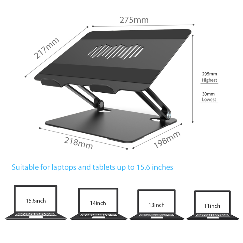
Computer Monitor Stand, the multi-point silicone support surface is more non-slip, and the multi-point soft silicone design prevents the computer from scratching while anti-slip. Laptop Stand Amazon is lightweight design, the weight of about 10kgs is equivalent to the weight of a large number of mobile phones, easy to store and go whenever you want.
Monitor Stand Riser,Metal Desk Monitor Stand Riser,Dual Monitor Riser Stand,Universal Monitor Stand Riser Shenzhen ChengRong Technology Co.,Ltd. , https://www.chengrongstand.com
Introduction The MAX3421E is a USB host / peripheral controller, that is, when working as a host, it uses a double-buffered transmit FIFO to send data to the USB peripheral. This pair of FIFOs is controlled by two registers:
R2: NDFIFO, FIFO data register
R7: SNDBC, byte count register
The microcontroller repeatedly writes the SNDFIFO register R2 to write up to 64 bytes of data to the FIFO. Then, the microcontroller writes to the SNDBC register again to complete the following three tasks: Specify the number of bytes to be sent in the MAX3421E SIE (Serial Interface Engine) FIFO. Connect SNDFIFO and SNDBC registers to USB logic for USB communication. Clear the SNDBAVIRQ interrupt flag. If the second FIFO can be used for µC loading, then SNDBAVIRQ will immediately re-trigger. 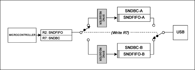
Figure 1. SNDFIFO register and SNDBC register load a pair of "ping-pong" FIFO and byte count registers
As shown in Figure 1, the first FIFO byte is not generated by the physical FIFO, but by the synchronization register used to tune the two internal clocks to synchronize them. One clock is used for the microcontroller and the other clock is used for USB logic.
Single-buffer transmission programming For those simple transmissions with no bandwidth and strict requirements, it is relatively simple for the firmware to send a data packet. The steps are as follows: Load bytes into SNDFIFO. Load bytes into the SNDBC register. Write OUT PID and endpoint number to the HXFR register, and the transfer starts. Wait for HXFRDNIRQ (Host sends a complete interrupt request). Read the transmission result code from the HRSL register. If it is ACK, it indicates that the transmission has been completed. If it is NAK, it will go to the next step. Load the first FIFO byte again and restart the transmission: write SNDBC = 0 and return a dummy value under the control of the microcontroller to switch the FIFO containing OUT data. Only the first FIFO byte is rewritten into the SNDFIFO register, and this byte enters the SYNC register in Figure 1. Write the number of bytes of the retransmitted data packet to the SNDBC register again, so that the FIFO can be switched back to the USB side, and USB communication is resumed. Go to step 3 and restart the packet. It can be seen from step 4 that the process belongs to single buffer transmission. Because of the need to wait for step 4 to complete, the microcontroller does not need to load the second FIFO when the first FIFO moves from the MAX3421E SNDFIFO to the USB peripheral.
If you use MAX3421E version 1, you also need to perform step 6, so every time you repeat the USB OUT transfer, the synchronization trigger must be re-initialized.
Double-buffered transfer programming When long data sets consisting of multiple 64-byte data packets are transferred from a USB host to a USB peripheral, using double buffering can improve performance. When the SNDFIFO is connected to the USB to send a data packet, the microcontroller simultaneously loads the next 64-byte data packet into other SNDFIFOs, thereby improving system performance. However, its program flow is slightly more complicated than single buffer transmission. In some cases, it is necessary to trigger the FIFO (such as when the NAK signal is obtained), reload the first byte and rewrite the byte count register to return it to the initial position, which requires the program to track the two buffers of data at any time. Figure 2 shows a possible flow of double-buffered transmission. This application note finally gives the Send_OUT_Record () function to implement the process shown in Figure 2. 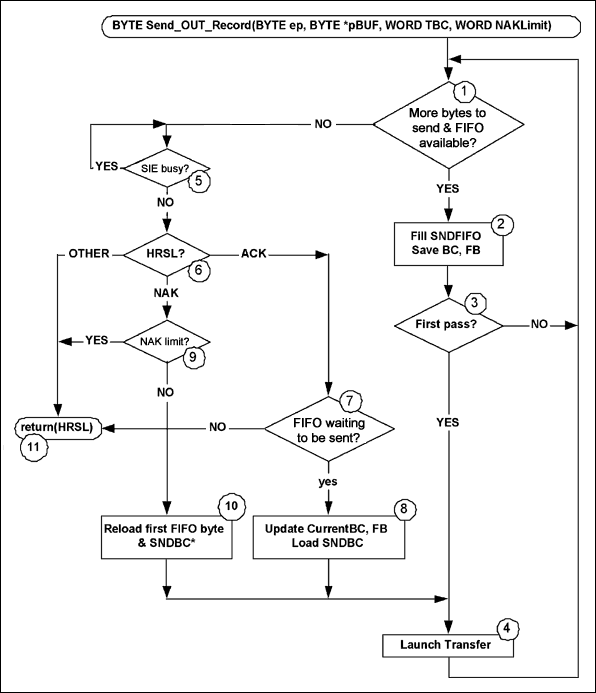
Figure 2. Double-buffered OUT packet transmission process
The right loop (step 1 to step 4) loads the USB data into the FIFO; from step 5 onward, the left loop allocates the FIFO through USB and processes the NAK retry. The "First pass?" Judgment (step 3) ensures that the USB transfer starts immediately after the main controller loads the first SNDFIFO. When designing the flow chart, the FIFO loading priority is higher than the sending priority, so the double buffering performance can still be maintained.
This process is best considered from the following three aspects: Send a data packet (1 to 64 bytes of total payload). Send two packets (65 to 128 bytes total payload). Send three or more data packets (129 or more bytes total payload). Please refer to the Send_OUT_Record () function routine given at the end of this application note. The calling program needs to transfer 4 parameters to this function: ep, the terminal number assigned to the OUT packet * pBUF, the buffer pointer TBC filled with data bytes Total number of bytes sent (number of bytes in the buffer) NAKLimit, the number of consecutive NAK responses received from the peripheral before stopping and returning. This function returns the MAX3421E host calculation result code register read when the last packet was sent (HRSL) value. If the transmission is successful, the value will be "ACK", if the NAK limit is exceeded, or an error code is generated due to other problems, the value will be "NAK".
Send an OUT packet. When the number of bytes sent is equal to or less than 64 bytes, loop from step 1. If the result of step 1 is true, the SPI host writes to SNDFIFO. If you need to use BC and FB in step 10, that is, when the peripheral responds to OUT transmission with "NAK", the function saves the number of bytes (BC) and the first byte of SNDFIFO (FB). Since this is the first data transfer, the function starts OUT transfer from step 4. Return to step 1 until no bytes need to be sent, and then the function waits for the transmission to complete in step 5 and tests the device response in step 6. If an ACK is obtained at this point, step 7 detects that no data needs to be sent, and the function returns at step 11. However, if NAK is obtained at this point, the NAK limit value is tested in step 9, and if the limit value is exceeded, the data packet is retransmitted in steps 10 and 4.
Send two OUT data packets. If the number of bytes sent is between 65 and 128, the function starts looping again from step 1. As mentioned above, the function fills the first SNDFIFO first, and transfers from step 2 to step 4 immediately. Then the function returns to step 1 and finds that there is still data waiting to be sent, so in step 2 the SNDFIFO is filled again. Since this is not the first transmission, the function cannot start transmitting the next data packet in step 4. When returning to step 1 again, the first SNDFIFO transmits the first data packet via USB, and at the same time, the second data packet is still in the second SNDFIFO, ready for transmission. It should be noted that in step 2, the function actually saves two sets of BC / FB data (byte count and the first byte of FIFO), one set is the SNDFIFO currently being transmitted, and the other set is the The data to be transmitted waiting in the SNDFIFO. If there is no data to send (and both SNDFIFOs are full of data), the control flow goes to step 5.
The function waits for the first data packet to be transmitted in step 5, and then determines the transmission result in step 6. As mentioned above, if the data packet is "NAK'd", the function reloads the pending BC / FB value into the FIFO and byte count register in step 10, retransmits the data packet in step 4, and the flow branches back to Step 5 (through step 1), wait for the transfer to complete. Each time a NAK is generated, follow steps 5-6-9-10-4-5 until the ACK is received or the NAK limit is reached.
If the peripheral device acknowledges (ACK) OUT transmission, the function tests whether the process is terminated in step 7. If it is not completed, the function flow goes to step 8 to send the next data packet waiting in the second SNDFIFO. In step 8, the function performs multiple tasks: if you need to load "pending" BC / FC values ​​in step 10, copy those values ​​to the "current" BC / FC variable; by loading the current number of bytes, switch the Two SNDFIFOs to USB; start to transfer OUT data in step 4. Each time a NAK signal is received, it operates cyclically as described above. If an ACK response is received during steps 7 to 11, the function exits.
Sending three or more OUT data packets Before one data packet is being sent and another data packet is about to start sending (waiting for the second SNDFIFO), the function basically follows the process of sending two data packets previously . Every time the function starts another data packet in step 4, it is judged in step 1 whether there is still data to be loaded into the SNDFIFO. Step 2 can only be entered if there is still data to be sent and the FIFO is valid in the program flow. Because the "write SNDFIFO" cycle in steps 1 to 3 has a higher priority than the "send FIFO" cycle in steps 5 ... 4, data is always written to the SNDFIFO when it is transferred via USB, thereby achieving double buffering.
performance 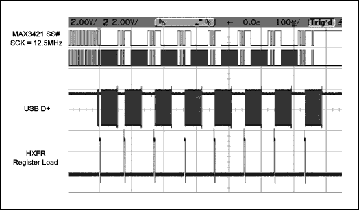
Figure 3. The oscilloscope curve of the MAX3421E loading and sending USB packets
Figure 3 shows the oscilloscope curve superimposed when using the Send_OUT_Record () function to load and send 64-byte OUT data packets. The size of the data is 512 bytes, consisting of 8 64-byte data packets. It can be seen from the figure that the peripherals connected to the MAX3421E do not generate NAK signals, so the maximum transmission bandwidth can be measured, and the oscilloscope can capture the entire transmission process at once.
The top two curves are curves for the SPI host (the SPI hardware has ARM7) to load 64 bytes of data into the MAX3421E SNDFIFO through the SPI port. Each time the SNDFIFO is written, the SS # (slave select) line is low and the SCK (serial clock) pulse is 65 x 8, each time the command byte is loaded, 8 clock pulses are provided to the 64-byte data . Before the curve starts, the first SNDFIFO load ends, so Figure 3 shows the situation when the SNDFIFO is loaded seven times.
The third curve is the USB D + signal, indicating that the 64-byte OUT data packet is being transmitted from the host MAX3421E to the external device via USB. The bottom curve is a pulse, indicating that ARM7 is loaded into the MAX3421E HXFR register and transmission begins.
It should be noted that: shortly after the start of the USB data packet, ARM7 begins to load the second SNDFIFO, and at the same time the USB data packet is transmitted on the bus. This double buffering process can greatly improve the transmission bandwidth.
Bandwidth test 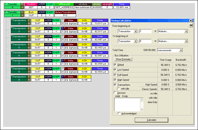
Figure 4. Figure 3 CATC (LeCroy) and bus analysis results during transmission
As shown in Figure 4, the Send_OUT_Record () function transmits 521 bytes of data at a rate of 6.76Mbps. For reference, a USB full-speed USB thumb drive connected to a PC uses a UHCI USB controller (USB's only accessory) to transmit 512 bytes of data at a rate of 5.94Mbps.
Precautions in solution implementation The code examples provided below are written and tested using the Maxim USB function library. For a detailed description of the Maxim USB function library, see Application Note 3936, "Maxim USB Library". The library tool includes the MAX3421E and MAX3420E USB peripheral controllers. To test the firmware, use a USB cable to connect the MAX3421E host to the MAX3420E peripheral, and comment out the statement marked "* 1 *" to make the MAX3420E accept each OUT transmission (no NAK).
Note: Future versions of the MAX3421E will no longer involve FIFO reloading. Just rewrite the HXFR register, MAX3421E can restart an OUT packet. This improvement no longer requires the Send_OUT_Record () function.
Send_OUT_Record () function example // ******************************************* ************************************ // Send an OUT record to end point 'ep'. / / pBuf points to the byte buffer; TBC is total byte count. // NAKLimit is the number of NAKs to accept before returning. // // Returns HRSL code (0 for success, 4 for NAK limit exceeded, HRSL for problems) / / ************************************************* ****************************** // BYTE Send_OUT_Record (BYTE ep, BYTE * pBuf, WORD TBC, WORD NAKLimit) {staTIc WORD NAKct, rb; // Buf index, NAK counter, remaining bytes to send WORD bytes2send; // temp BYTE Available_Buffers; // Remaining buffers count (0-2) BYTE FI_FB; // Temporary FIFO first byte staTIc BYTE CurrentBC; / / Byte count for currently-sending FIFO staTIc BYTE CurrentFB; // First FIFO byte for currently-sending FIFO staTIc BYTE PendingBC; // Byte count for next 64 byte packet scheduled for sending static BYTE PendingFB; // First FIFO byte for next 64 byte packet schedul ed for sending BYTE dum; BYTE Transfer_In_Progress, FirstPass; // flags // NAKct = 0; Available_Buffers = 2; rb = TBC; // initial remaining bytes = total byte count FirstPass = 1; // do {while ((rb! = 0) && (Available_Buffers! = 0)) // WHILE there are more bytes to load and a buffer is available {// Pwreg (rEPIRQ, bmOUT1DAVIRQ); // * 1 * enable the 3420 for another OUT transfer FI_FB = * pBuf; // Save the first byte of the 64 byte packet bytes2send = (rb> = 64)? 64: rb; // Lower of 64 bytes and remaining bytes rb-= bytes2send; // Adjust 'remaining bytes' Hwritebytes (rSNDFIFO , 64, pBuf); pBuf + = 64; // Advance the buffer pointer to the next 64-byte chunk Available_Buffers-= 1 // One fewer buffer is now available // if (Available_Buffers == 1) // Only one has been loaded {CurrentBC = bytes2send; CurrentFB = FI_FB;} else // Available_Buffers must be 0, both loaded. {PendingBC = bytes2send; PendingFB = FI_FB;} // if (FirstPass) {FirstPass = 0; Hwreg (rSNDBC, CurrentBC) ; // Load the byte count L7_ON // L ight 7 is used as scope pulse Hwreg (rHIRQ, bmHXFRDNIRQ); // Clear the IRQ Hwreg (rHXFR, (tokOUT | ep)); // Launch an OUT1 transfer L7_OFF}} // While there are bytes to load and there is space for them // do // While a transfer is in progress (not yet ACK'd) {// while ((Hrreg (rHRSL) & 0x0F) == hrBUSY); // Hang here until current packet completes while (( Hrreg (rHIRQ) & bmHXFRDNIRQ)! = BmHXFRDNIRQ); dum = Hrreg (rHRSL) & 0x0F; // Get transfer result if (dum == hrNAK) {Transfer_In_Progress = 1; NAKct + = 1; if (NAKct == NAKLimit) return (hrNAK); else {Hwreg (rSNDBC, 0); // Flip FIFOs Hwreg (rSNDFIFO, CurrentFB); Hwreg (rSNDBC, CurrentBC); // Flip FIFOs back L7_ON // Scope pulse Hwreg (rHIRQ, bmHXFRDNIRQ); / / Clear the IRQ Hwreg (rHXFR, (tokOUT | ep)); // Launch an OUT1 transfer L7_OFF}} else if (dum == hrACK) {Available_Buffers + = 1; NAKct = 0; Transfer_In_Progress = 0; // Finished this transfer if (Available_Buffers! = 2) // Still some data to send {CurrentBC = PendingBC; CurrentFB = PendingFB; Hwreg (rSNDBC, CurrentBC); L7_ON // Scope pulse Hwreg (rHIRQ, bmHXFRDNIRQ); // Clear the IRQ Hwreg (rHXFR, (tokOUT | ep)); // Launch an OUT1 transfer L7_OFF}} else return (dum); } while (Transfer_In_Progress);} while (Available_Buffers! = 2); // Go until both buffers are available (have been sent) return (0);}
MAX3421E version 1 and 2 host OUT transmission
Abstract: This application note discusses the host USB controller MAX3421E versions 1 and 2. The MAX3421E uses double-buffered transmit FIFOs to send data to USB peripherals. In versions 1 and 2 of the device, it is important to consider the programming of the OUT transfer. This application note details the sending mechanism. And give the single buffer and double buffer OUT transmission routines.