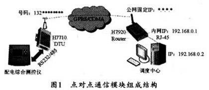
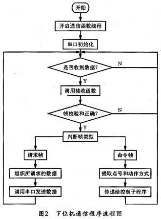
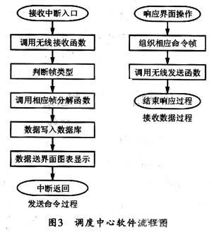
The Design of Communication Module of the Comprehensive Distribution Control Instrument 0 Preface With the development of economy, many distribution houses with energy-saving significance get rid of manual meter reading, and use distribution network monitoring and control instruments and other distribution network operation status monitoring equipment to realize the management and analysis of electricity consumption data. The distribution room status information collected by a single distribution integrated measurement and control instrument often needs to be quickly transmitted to the main station of the dispatch center for analysis and processing by dispatchers or dispatch software for reasonable power grid dispatching and accident handling. However, the geographical dispersion of the distribution room makes the construction and expansion of the distribution network data transmission network very difficult. The traditional solution is to use the telephone line with a wide coverage to transmit the data of the distribution network, but it has the disadvantages of small capacity and slow speed. With the increasing number of electrical equipment and distribution rooms, it has been unable to meet the distribution network. Data transmission requirements of dispatch automation systems. In recent years, the wireless network transmission technology is more suitable for data transmission in the distribution network due to its large transmission capacity and the need to construct a new data transmission network for the newly added distribution integrated measurement and control instrument. This paper presents the design scheme of such a wireless communication module based on CDMA 1X network. 1 Working process of communication module The schematic diagram of the communication process of this distribution integrated measurement and control instrument sending grid parameter information to the dispatch center is shown in Figure 1. As the lower computer, the integrated power distribution monitoring and control instrument in the figure first adopts a development platform combining ARM and μC / OS-II real-time operating system to realize the data acquisition function of the distribution network, the calculation function of the grid parameters, the control function of the capacitor switching and the lower Machine communication function. Then the lower computer communication program assembles the grid parameter data to be transmitted to the upper computer into frames, and transmits them to the H7710DTU wireless data transmission unit through the serial port. For H7710DTU, this frame is user data. It automatically assembles the user data into a data frame that complies with the IS-95A and IS-95BCDMA air interface standards and sends it out through the antenna. After the H7920 CDMA 1X router receives the data frame sent by the H7710DTU with which it establishes a wireless connection, it automatically extracts the user data from the frame according to the IS-95A and IS-95B standards and transmits it to the host computer through the RJ-45 network port Do treatment. The transparent channel used by the H7710DTU and H7920 CDMA 1X routers in the system for data transmission between the integrated power distribution measurement and control instrument and the dispatch center can complete the reliable delivery of user data. Figure 1 only shows the connection between a comprehensive distribution measurement and control instrument and the host of the dispatch center. In fact, the number of comprehensive distribution measurement and control instruments can be expanded at will, as long as the amount of data transmitted simultaneously at multiple points does not exceed 100 kB / s (CDMA 1X Actual application bandwidth). It can be seen from Figure 1 that the wireless communication module designed in this paper is composed of three parts, namely: the lower computer communication program part in the power distribution integrated measurement and control instrument, the wireless data channel part composed of H7710DTU and H7920 wireless router, and the host in the dispatch center Upper computer software part. The wireless data channel part is the communication basis of the other two parts. It is used to complete the functions of the network layer, data link layer, and physical layer. It is responsible for establishing and maintaining the data channel from one (or more) lower computer to the upper computer. Once the part is configured, it can work automatically. The upper and lower computers are peer-to-peer communication entities and are located at the application layer. There is no need to consider the specific working process of the lower-level data channel. You only need to input and output user data through the serial port or network port. The communication protocol is organized into frames to communicate and respond to the commands of the upper computer. The upper computer is mainly responsible for extracting the grid parameter data in the frame according to the same power protocol and sending commands to the lower computer to control the actions of related equipment. 2 wireless data transmission channel configuration The wireless data transmission channel in the scheme of this article is composed of two parts: H7710DTU wireless data transmission unit and H7920 wireless router of Shenzhen Hongdian Technology Development Co., Ltd. Among them, DTU is a wireless device specially used to transmit serial data through GPRS or CDMA 1X network. The wireless router is a network device based on GPRS / CDMA1X public mobile network platform to wirelessly access the Internet. 2.1 H7710DTU configuration The H7710DTU needs to be inserted with a SIM card before it can be used. In this solution, the Unicom SIM card is used, the number is 132 ********. The configuration work mainly includes four groups of parameters, namely: mobile service center settings, data terminal unit settings, data service center settings (DSC), user serial port settings. The mobile service center is used to store the service information of the mobile network. The first type is the service code, that is, the public unified access number provided for each mobile network operator. The Unicom CDMA user is set to the number "# 777"; the other type is the user The name and user password are used to verify identity during the dialing process. The Unicom CDMA user is set to "card" and the password is also "card". The data terminal unit is used to distinguish multiple DTUs, mainly including: a. DTU identification code, give the DTU terminal a name to facilitate user identification at the center. b. Local communication port refers to the local communication port number for DTU to send and receive data. The data service center is used to specify the data service center (DSC) information that the DTU wants to establish a connection, mainly including the public network IP address obtained by connecting the DSC server to the Internet and the communication port number of the DSC server. The user serial port setting is used to match the input mode of the user terminal serial port, mainly including baud rate, data bit, parity bit and stop. This setting should be consistent with the serial port setting of the integrated power distribution measurement and control instrument. After the H7710DTU is configured, as long as it is powered on and the DSC is online, the DTU will automatically dial and establish a data connection channel with the H7920 wireless router. 2.2 Configuration of H7920 wireless router The H7920 wireless router also requires a SIM card to be used. In this solution, the Unicom SIM card is used. The configuration work mainly includes network parameter setting and routing parameter setting. The network parameter setting is used to specify the information of the local area network and mobile network to which the wireless router is connected, mainly including: a. LAN interface parameters, you can configure the LAN IP address as needed. b. The mobile network parameters are the same as the settings of the H7710DTU mobile service center. Routing parameter setting refers to determining the physical interface address to which IP packets need to be sent through the routing table. If the user's network has multiple routers and subnets, the routing table needs to be enabled so that the data packets can take the appropriate path and that different subnets can communicate with each other. H7920 wireless mobile router will detect the operator's network immediately after power on, and under the premise that the network signal is normal, dial the connection to the operator's network server according to the set number (China Unicom: # 777), Then after going through a series of protocol authentications and the username / password verification is passed, the operator's web server will assign an IP address to the mobile router, and the PPP dial-up connection is completed. 3 Design of the communication program of the lower computer The communication module lower computer adopts M2020-FNU20 industrial control module of Guangzhou Zhiyuan Electronics Co., Ltd. as the core development board. M2020-FNU20 is based on the LPC2220 (ARM7TDMI) industrial-grade microcontroller, embeds μC / OS-II real-time operating system and driver support library for all hardware, and can operate the hardware through API functions. The communication program of the lower computer in this paper is developed in the ADS1.2 integrated development environment, and is written in C language and API functions provided by the development board. The main functions completed by the lower computer communication program are: a. Call the API to open, close and set the serial port; b. Call API to receive and send data; c. According to the agreed power protocol, the grid parameters measured and calculated by the distribution integrated measurement and control instrument are organized into data frames and sent; d. Receive the command frame issued by the host computer, extract the control information, and send it to the device execution mechanism. The real-time grid parameters collected by the power distribution integrated measurement and control instrument are stored in the Flash memory in the form of files. When the dispatching center polls the power distribution integrated measurement and control instrument, the communication program is responsible for interpreting the data request command issued, and organizing the grid parameter data to be uploaded into one or more data frames according to the agreed power communication protocol, with the specified interaction Way to the dispatch center software. The program flow is shown in Figure 2. 4 Software design of dispatch center The upper computer software DSC (Data Service Center) of the dispatch center is mainly used for receiving DTU data and sending data to the DTU. The communication between DSC and DTU needs to be completed using the dynamic library wcomm_dll.dll file in the wireless router development kit. This file contains all the API functions required for communication with DTU, including service startup, data transmission, data reception, and service shutdown. Wait. DSC is actually a data processing software based on the functions provided by wcomm_dll.dll. Its main functions are as follows: (1) Call the API to start the service and stop the service; (2) Call API to receive data and send data to DTU; (3) Extract the grid parameter information from the received data frame according to the agreed power protocol: (4) Display and storage of grid parameter information; (5) According to the input of the dispatch operator, organize and issue control command frames. According to the different data type frames uploaded by the power distribution integrated measurement and control instrument, the corresponding frame processing function is called, and the telemetry, remote signal, energy pulse amount and event sequence records are extracted separately, and displayed on the DSC interface for scheduling by graph Personnel view, and save the data back to the Access database. In this solution, Delphi 7 integrated development environment is used, ADOConnect component is used to rent ADODataSet component and Access database is connected to read and write to the database, and the data on the interface is displayed in chart mode using DataSource component and DBGrid component to complete. The software program flow of its dispatch center is shown in Figure 3. 5 Conclusion Under the current energy shortage situation, the construction of distribution network dispatching automation system has important energy-saving significance. The communication module of integrated power distribution measurement and control instrument based on CDMA 1X wireless network designed in this paper has been verified by experiments. It has fast communication speed, high reliability, and is very convenient to configure and expand. It can meet the data transmission requirements of distribution network dispatching automation system. It has certain reference value to promote the construction of distribution network dispatching automation system.
24v power supply, the current range is 2A-9.2A, the max power is 220w. We also can meet your specific requirement of the prodcuts.The material of this product is PC+ABS. All condition of our product is 100% brand new.
Our products built with input/output overvoltage protection, input/output overcurrent protection, over temperature protection, over power protection and short circuit protection. You can send more details of this product, so that we can offer best service to you!
24V Power Supply,24V Pc Power Supply,24V Dc Power Supply ,24V Power Supply For Pc Shenzhen Waweis Technology Co., Ltd. , https://www.waweisasdapter.com