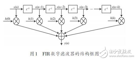
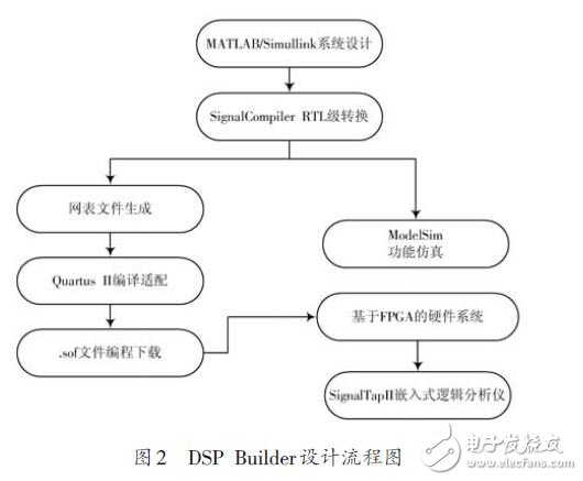
In the Matlab/Simulink environment, the DSP model is used to build the FIR model. The FIR filter is designed according to the FDATool tool. Then the system level simulation and ModelSim function simulation are carried out. The simulation results show that the digital filter has good filtering effect. The model is converted into VHDL language by SignalCompiler and added to the hardware design of the FPGA. The real-time result waveform of the digital filter is obtained from the virtual logic analysis tool SignalTapII in Quartus II software. The result is in line with expectations. 0 Preface In the process of information signal processing, digital filters are the most widely used method in signal processing. By filtering operations, a set of input data sequences is transformed into another set of output data sequences, thereby realizing changes in signal properties in the time domain or frequency domain. Commonly used digital filters can be divided into finite impulse response (FIR) filters and infinite impulse response (IIR) filters. Among them, the FIR digital filter has a strict linear phase, and the non-recursive structure also ensures the stability of the operation. In applications with high real-time requirements, programmable chip FPGAs are used to achieve high speed, high precision, and high flexibility compared to DSP chips or dedicated chip implementation methods. In this paper, when adopting a method based on FPGA and DSP Builder to design FIR digital filter, the hierarchical and modular design idea is adopted, and the design and development flow of DSP Builder is followed. The model is built in Matlab/Simulink and the system level is implemented. Simulation, Verilog language conversion, ModelSim simulation verification, real-time test of FIR digital filter. 1 FIR digital filter basic principle and structure For a FIR filter system, its impulse response is always finite, and its system function can be written as: Where x(n) is the input sample sequence; h(i) is the filter coefficient; k is the filter order; y(n) is the output sequence of the filter. Figure 1 is a block diagram showing the structure of a k-order FIR digital filter. 2 FIR digital filter design flow The design process mainly involves the development and design of tool software such as Matlab/Simulink, DSPBuilder and Quartus II. The entire design process, from system description to hardware implementation, can be done in a complete design environment, as shown in Figure 2. (1) Design input in Matlab/Simulink, that is, create a model file with mdl extension in Matlab's Simulink environment, and graphically call Altera DSP Builder and other graphic modules in the Simulink library to form system level or Algorithm level design block diagram (or Simulink design model). (2) Using Simulink's graphical simulation and analysis functions, analyze the correctness of this design model and complete the model simulation, also called system level simulation. (3) A key step in the DSP Builder design and implementation, the Signal file is converted into a general hardware description language Verilog file through Signal-Compiler. (4) The converted Verilog source code is functionally simulated with ModelSim software to verify the correctness of the Verilog file. The next few steps are to synthesize, compile, and adapt the Verilog RTL code and simulation files generated by the above design in the Quartus II tool software. The sof file is loaded into the FPGA hardware system. iDealTek-Electronics has accumulated rich application experience and design technical knowledge in the field of High-voltage power supplies, from Linear High Voltage Power Supplies based on power frequency transformers to Switching High Voltage power supplies based on IGBT components, from 60KV, 1KW High Voltage Power Module, to 5KV ~ 40KV, 1KW 2U Laboratory High-voltage power supplies, and to 5KV ~ 60KV, 2KW 4U and 5KV ~ 100KV, 6U rack-mounted capacitor charging high-voltage power supplies, and then to floor-standing cabinet-type high-current high-power high-voltage power supplies, all our high voltage power supplies are featured for high reliability, excellent high-voltage output stability and low-ripple electronic characteristics. HV Power Supplies, High-voltage Power Supplies, High Voltage DC Power Supplies, HV PSU, High Voltage Power Module Yangzhou IdealTek Electronics Co., Ltd. , https://www.idealtekpower.com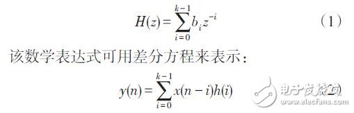


Through the reliable and durable operation panel on the front panel of the high-voltage power supply, the output voltage and current can be easily set and controlled. The high-precision LED or LCD ensures intuitive and high-precision high-voltage output measurement functions. Our high-voltage power supplies can be equipped with a wealth of remote-control interfaces, such as RS232 / RS485 /DB15 / DB25 / DB50 analog signal interface, etc. for remote high-voltage enable and inhibit, high-voltage output control programming and data monitoring.
Our HV power supplies have complete built-in protection functions, such as overvoltage protection, ARC protection, load discharge protection, over heat protection, etc. The protection mechanism can start in transient time to ensure the safety and reliability of the power supply itself and customer loads under high-voltage output.

At present, our high voltage power supplies are widely used in high-voltage laboratories, capacitor charging, electron beam, ion implantation, FUSION power generation and other industries.