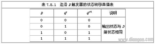
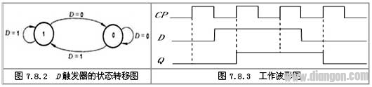
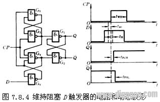
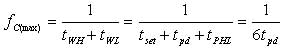
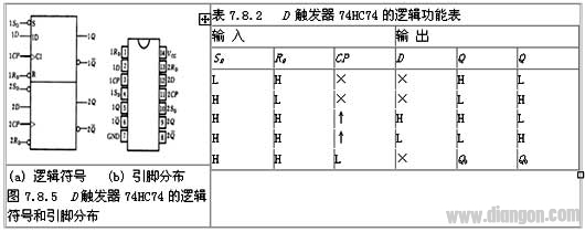
Edge D trigger: When the master-slave trigger triggered by a negative edge is active, the input signal must be added before the positive edge. If an interfering signal is present at the input during CP high, it is possible to make the state of the flip-flop error. The edge trigger allows the input signal to be added just before the CP trigger edge. In this way, the time at which the input is disturbed is greatly reduced, and the possibility of interference is reduced. Edge D flip-flops are also referred to as sustain-block edge D flip-flops. Circuit Structure: The flip-flop consists of six NAND gates, where G1 and G2 form the basic RS flip-flop. working principle: SD and RD are connected to the inputs of the basic RS flip-flops, which are preset and clear, respectively, active low. When SD=0 and RD=1, regardless of the state of the input terminal D, Q=1, Q=0, that is, the flip-flop is set to 1; when SD=1 and RD=0, the state of the flip-flop is 0. SD and RD are also commonly referred to as direct set and set zero. We set them to have been added to a high level and do not affect the operation of the circuit. The working process is as follows: 1. When CP=0, the NAND gates G3 and G4 are blocked, and the output Q3=Q4=1, the state of the trigger is unchanged. At the same time, since the feedback signals of Q3 to Q5 and Q4 to Q6 open the two doors, the input signal D can be received, Q5=D, and Q6=Q5=D. 2. The flip-flop flips when the CP changes from 0 to 1. At this time, G3 and G4 are turned on, and the states of their inputs Q3 and Q4 are determined by the output states of G5 and G6. Q3=Q5=D, Q4=Q6=D. It is known from the logic function of the basic RS flip-flop that Q=D. 3. After the trigger is flipped, the input signal is blocked when CP=1. This is because after G3 and G4 are turned on, their outputs Q3 and Q4 are complementary, that is, there must be one. If Q3 is 0, the feedback line that is output to the G5 input via G3 blocks G5, that is, it is blocked. D The path to the basic RS flip-flop; this feedback line acts to maintain the flip-flop in the 0 state and prevent the flip-flop from becoming the 1 state, so the feedback line is called the 0-hold line and the 1 block line is set. When Q4 is 0, G3 and G6 are blocked, and the path from the D end to the basic RS flip-flop is also blocked. The Q4 output to the G6 feedback line acts to maintain the flip-flop in the 1 state, which is called the set-one maintain line; the Q4 output to the G3 input feedback line acts to prevent the flip-flop from being set to 0, which is called the 0-block line. . Therefore, this trigger is often referred to as a sustain-blocking trigger. In short, the trigger accepts the input signal before the positive edge of the CP, triggers the flip when the positive edge is skipped, and the input is blocked after the positive edge. The three steps are completed after the positive edge, so there is an edge trigger. . Compared with the master-slave flip-flop, the edge trigger of the same process has stronger anti-interference ability and higher working speed. Functional description State transition truth table 2. Characteristic equation Qn+1=D 3. State transition diagram Pulse characteristics: 1. Settling time: It can be seen from the circuit of Figure 7.8.4 that the blocking trigger is maintained. Since the CP signal is applied to the gates G3 and G4, the state of the gates G5 and G6 must be stably established before the rising edge of the CP. . After the input signal reaches the D terminal, the output state of the G5 output delay time can be established, and the output state of the G6 needs to be established after the transmission delay time of the two-stage gate circuit. Therefore, the input signal of the D terminal must be Arrived on the rising edge of CP, and the settling time should satisfy: tset≥2tpd. 2. Holding time: As shown in Figure 7.8.4, in order to achieve edge triggering, it should be ensured that the output state of gate G6 is unchanged during CP=1, and is not affected by the state change of D terminal. For this reason, in the case of D=0, after the rising edge of the CP arrives, the low level of the D terminal is allowed to change after the low level of the output of the gate G4 is returned to the input terminal of the gate G6. Therefore, the hold time of the input low level signal is tHL ≥ tpd. In the case of D=1, since the output of G3 blocks G4 after the rising edge of CP rises, the input signal is not required to remain unchanged, so the hold time tHH=0 of the input high level signal. 3. Transmission delay time: It is not difficult to calculate from Figure 7.8.3. It starts counting from the rising edge of CP, and outputs the transmission delay time tPHL from high level to low level and from low level to high level. The transmission delay time tPLH is: tPHL=3tpd tPLH=2tpd 4. Maximum clock frequency: In order to ensure that the synchronous RS flip-flop composed of the gates G1 G G4 can be reliably flipped, the duration of the CP high level should be greater than tPHL, so the width tWH of the high level of the clock signal should be greater than tPHL. In order to ensure that the new output levels of the gates G5 and G6 are stably established before the next CP rising edge arrives, the duration of the CP low level should not be less than the sum of the transmission delay time of the gate G4 and the tset, that is, the clock signal is low. The flat width tWL ≥ tset + tpd, so get: Finally, in the actual integrated trigger, each gate transmission time is different and simplified in different forms, so the results discussed above are only qualitative physical concepts. Its true parameters are determined experimentally. Integrated trigger: There are many types of stereotyped products with integrated D flip-flops. Here, the double-dix trigger 74HC74 is introduced. In fact, there are many types of 74 models, such as 7474 and 74H74. Through the logic symbols in Figure 7.8.5 and the logic function table of D flip-flop 74HC74, we can see that HC74 is an edge trigger with preset, clear input and upper edge trigger. In summary, the edge D flip-flops are summarized as follows: 1. Edge D flip-flop has the function of receiving and memorizing signals, also known as latch; 2. Edge D flip-flop belongs to pulse trigger mode; 3. Edge D flip-flop has no constraint and one change phenomenon, anti-interference performance Ok, work fast. D flip-flop working principle The master-slave JK flip-flop receives the signal during the CP pulse high level. If there is an interference signal at the input end during the CP high level, it is possible to cause the trigger to generate an error that does not match the logic function table. status. The circuit structure of the edge trigger enables the trigger to receive the signal immediately before the effective trigger edge of the CP pulse, and the state transition occurs after the effective trigger edge arrives. The trigger of the circuit structure greatly improves the anti-interference ability and the circuit operation. reliability. The following describes the working principle of the edge trigger by taking the maintenance of the blocking D flip-flop as an example. 1 When CP=0, the NAND gates G3 and G4 are blocked, the output is 1, and the state of the flip-flop is unchanged. At the same time, since the two gates G5, G6 are turned on by the feedback signals to G5 and G6, the input signal can be received, so that =, ==.
ZGAR AZ Vape Pods 5.0
ZGAR electronic cigarette uses high-tech R&D, food grade disposable pod device and high-quality raw material. All package designs are Original IP. Our designer team is from Hong Kong. We have very high requirements for product quality, flavors taste and packaging design. The E-liquid is imported, materials are food grade, and assembly plant is medical-grade dust-free workshops.
From production to packaging, the whole system of tracking, efficient and orderly process, achieving daily efficient output. WEIKA pays attention to the details of each process control. The first class dust-free production workshop has passed the GMP food and drug production standard certification, ensuring quality and safety. We choose the products with a traceability system, which can not only effectively track and trace all kinds of data, but also ensure good product quality.
We offer best price, high quality Pods, Pods Touch Screen, Empty Pod System, Pod Vape, Disposable Pod device, E-cigar, Vape Pods to all over the world.
Much Better Vaping Experience!
Pods, Vape Pods, Empty Pod System Vape,Disposable Pod Vape Systems ZGAR INTERNATIONAL TRADING CO., LTD. , https://www.sze-cigarette.com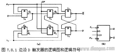
The logic diagram and logical symbols for maintaining a blocking edge D flip-flop are shown in Figure 9-7. The flip-flop is composed of six NAND gates, wherein G1 and G2 form a basic RS flip-flop, G3 and G4 form a clock control circuit, and G5 and G6 constitute a data input circuit. The sum is directly set to 0 and directly set to 1 and the active level is low. When analyzing the working principle, set the sum to be high level, which does not affect the work of the circuit. The circuit works as follows. 
(a) Logic diagram (b) Logic symbol Figure 9-7 Maintain blocking type D flip-flop
2 When the CP changes from 0 to 1, the gates G3 and G4 are opened, and the state of their output sum is determined by the output states of G5 and G6. ==, ==. Known by the logic function of the basic RS trigger, =.
3 After the trigger is flipped, the input signal is blocked when CP=1. After G3 and G4 are turned on, their output and state are complementary, that is, there must be one. If it is 0, the feedback line output from G4 to G6 will block G6, that is, block D to basic RS trigger. The path of the device; the feedback line acts to maintain the flip-flop in the 0 state and prevent the flip-flop from becoming the 1 state. Therefore, the feedback line is referred to as a 0-hold line and a 1 block line is set. When G3 is 0, G4 and G5 are blocked, and the path from the D terminal to the basic RS flip-flop is also blocked; the G3 output terminal to the G5 feedback line serves to maintain the flip-flop in the 1 state, which is called the set-one maintenance line. The feedback line from the G3 output to the G4 input acts to prevent the trigger from being set to 0, which is called the 0 blocked line. Therefore, this trigger is called a hold blocking trigger.

