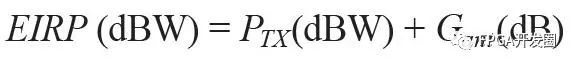
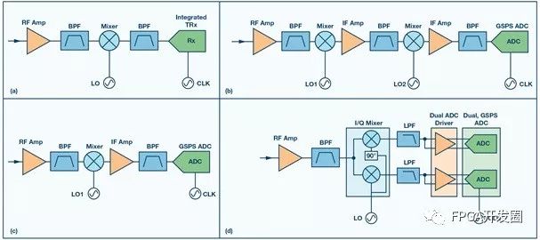
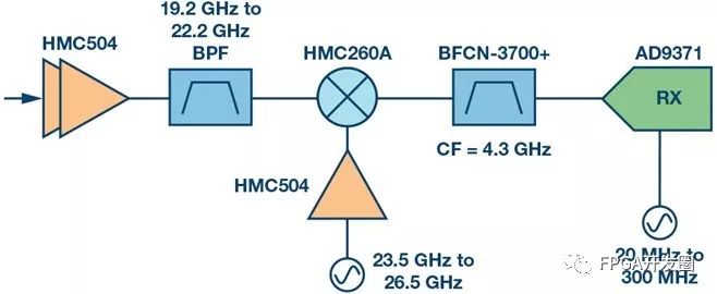
As the demand for global connectivity grows, many satellite communication (satcom) systems are increasingly adopting the Ka band, and the requirements for data rates are also rising. Currently, high-performance signal chains have been able to support multi-gigabit instantaneous bandwidth. There may be hundreds or thousands of transceivers in a system, and ultra-high throughput data rates have become a reality. In addition, many systems have begun to move from mechanically positioned static parabolic antennas to active phased array antennas. With the enhancement of technology and higher integration, the component size can be greatly reduced, and it can meet the needs of the Ka band. By forming nulls in the antenna pattern along the direction of the interfering signal, the phased array technique can also improve the interference reduction performance. The following will briefly describe some of the trade-off options that exist in existing transceiver architectures, as well as the applicability of different types of architectures in different types of systems. This analysis will decompose some of the key technical specifications of satellite systems and how to obtain the specifications of each component of the transceiver signal chain layer from these system-level specifications. 1 Break down technical specifications from system level analysis From a macro perspective, satellite communication systems need to maintain a certain carrier-to-noise ratio (CNR), which is the result of link budget calculations. Maintaining the CNR can guarantee a certain bit error rate (BER). The required CNR depends on many factors such as error correction, information encoding, bandwidth, and modulation type. After the CNR requirements are determined, the technical specifications of each receiver and transmitter can be decomposed down according to the requirements of the high-level system. In general, the first gain is the gain-system noise temperature (G/T) quality factor of the transceiver and the effective omnidirectional radiated power (EIRP) of the transmitter. For the receiver to derive the low-level receiver signal chain specification from G/T, the system designer needs to know the antenna gain and the system noise temperature, which is a function of the antenna pointing and receiver noise temperature, as shown in Equation 1. Based on this, the receiver temperature can be obtained using Equation 2. The noise figure of the receiver signal chain can then be calculated using Equation 3: After the receiver noise figure is known, a cascade analysis can be performed to ensure that the signal chain meets the requirements of these necessary technical specifications and that adjustments are required. For the receiver, the required EIRP is first determined based on the receiver's distance (ground-to-satellite or satellite-to-ground distance) and receiver sensitivity. Knowing the EIRP requirements requires a compromise between the output power of the transmit signal chain and the antenna gain. For high-gain antennas, the power consumption and size of the transmitter can be reduced, but at the expense of increasing the antenna size. EIRP is calculated by Equation 4. As long as the components used in the signal chain are carefully selected, the output power can be maintained unchanged and will not cause other important parameters to drop, such as interference with the output noise of other systems and out-of-band RF energy. Other important specifications for transmitters and receivers include: Instantaneous bandwidth: the spectral bandwidth that can be digitized at any time in the signal chain Power processing: The maximum signal power to be processed in the signal chain without degrading performance Phase coherence between channels: For emerging beamforming systems, ensuring phase predictability between channels simplifies beamforming signal processing and calibration Spurious performance: Ensure that the receiver and transmitter do not generate RF energy at undesired frequencies, so as not to affect the performance of the system or other systems Figure 1. Architecture comparison, (a) high IF (integrated TRx), (b) dual-conversion superheterodyne architecture (with GSPS ADC), (c) single-conversion superheterodyne architecture (with GSPS ADC), (d) direct Frequency conversion (with I/Q mixer). These and other specifications must be kept in mind during the design of the signal chain to ensure that high-performance systems are designed to meet the needs of any given application, whether it is a broadband multi-carrier aggregation hub or a single narrow-band handheld satellite communication terminal. 2 Common architecture comparison After determining high-level technical specifications, you can decide which signal chain architecture to use. One of the key specifications listed previously and that may have a significant impact on the architecture is the instantaneous bandwidth. This specification affects the analog-to-digital converter (ADC) of the receiver and the digital-to-analog converter (DAC) of the transmitter. In order to achieve high instantaneous bandwidth, the data converter must be sampled at a higher rate. As a result, the power consumption of the entire signal chain is generally increased. However, if the unit power consumption (W/GHz) is viewed, the power consumption will be reduced. . For systems with less than 100 Mhz bandwidth, it is best to use an infrastructure similar to Figure 1a in many cases. The architecture combines a standard down conversion stage with an integrated direct conversion transceiver chip. The integrated transceiver enables ultra-high integration, which greatly reduces size and power consumption. To achieve a bandwidth of 1.5 Ghz, the classic dual-conversion superheterodyne architecture can be combined with the most advanced ADC technology; as shown in Figure 1b. This is a mature, high-performance architecture with an integrated inverter stage for filtering out unwanted spurious signals. According to the received frequency band, a down conversion stage converts the received signal to an intermediate frequency (IF), and then uses another down conversion stage to convert the final intermediate frequency signal to a low frequency signal that the ADC can digitize. The lower the final IF, the higher the ADC performance, but at the cost of increased filtering requirements. In general, due to the increase in the number of components, the architecture is the largest and most power-consuming architecture among the four options mentioned in this paper. A similar option is shown in Figure 1c, where a single conversion stage is used to convert the signal to a high IF and sampled by the GSPS ADC. This architecture takes advantage of more RF bandwidth that can be digitized by the ADC, with little degradation in performance. The latest GSPS ADC on the market can directly sample up to 9 Ghz RF frequencies. In this option, the IF center is between 4 Ghz and 5 Ghz to achieve the best balance between signal chain filtering requirements and ADC requirements. The last option is shown in Figure 1d. The instantaneous bandwidth increase of this architecture is even larger, but the cost is very complicated and may cause the performance to decline. This is a direct-conversion architecture that uses a passive I/Q mixer that can output two IFs offset from each other by 90° at baseband. Each I and Q channel is then digitized with a dual channel GSPS ADC. In this case, instantaneous bandwidth up to 3 Ghz can be obtained. The main challenge of this option is to maintain quadrature balance between the I and Q paths as the signal propagates through the mixer, low-pass filter, and ADC driver. Based on specific CNR requirements, this trade-off may be acceptable. The above briefly describes the working principle of these receiver architectures from the macro level. The list does not exhaust all the circumstances, and various options can also be used together. Although the comparison does not involve the transmit signal chain, each option in Figure 1 has a corresponding transmit signal chain, and the trade-off is similar. 3 Ka-band satellite communication receiver example The above discussed the advantages and disadvantages of various architectures. Next, we can apply this knowledge to the real signal chain examples. At present, many satellite communication systems operate in the Ka band to reduce the size of the antenna and increase the data rate. This is especially important in high-throughput satellite systems. The following are examples of different architectures, and we will compare them in more detail. For systems that require an instantaneous bandwidth of less than 100 Mhz, such as Very Small Aperture Terminal (VSAT), the high-IF architecture of the integrated transceiver chip (AD9371) can be used, as shown in Figure 2. This design can achieve a low noise figure, and its design size is minimized due to high integration. Its performance is summarized in Table 1. Figure 2. High IF (Integrated TRx) with up to 100 MHz bandwidth. As a hub for multiple users of a satellite communications system, these systems may have to process multiple carrier signals simultaneously. In this case, the bandwidth or bandwidth/power of each receiver becomes very important. The signal chain shown in Figure 3 uses a high-speed ADC, the AD9208, a recently released high-sampling-rate ADC that can digitize instantaneous bandwidths up to 1.5 Ghz. In this example, to achieve a 1 Ghz instantaneous bandwidth, the IF is placed at 4.5 GHz. The bandwidth that can be achieved here depends on the filtering requirements of the anti-aliasing filter that precedes the ADC, but is generally limited to ~75% of the Nyquist zone (half the sampling rate). Figure 3. Single downconversion to high intermediate frequency with GSPS ADC. In systems requiring the highest instantaneous bandwidth and possibly at the expense of CNR, the signal chain shown in Figure 4 can be used. This signal chain uses an I/Q mixer, the HMC8191HMC8191, with an image rejection performance of ~25 dBc. In this case, image rejection performance is limited by the amplitude and phase balance between the I and Q output channels. This is a limiting factor for the signal chain without the use of more advanced Quadrature Error Correction (QEC) techniques. The performance of this signal chain is summarized in Table 1. It should be noted that the NF and IP3 performance is similar to other options, but the power/GHz index is the lowest of the three, and the size of the bandwidth that can be used at any time is also the best. Figure 4. Direct conversion with I/Q mixer and GSPS ADC. The three receiving options given here are shown in the table below, but it should be noted that this table does not list all possible options. The summary here is intended to show the differences between various signal chain options. In any given system, the final optimal signal chain may be either one of three or a combination of arbitrary options. Table 1. Comparison of Ka Band Receiver Details In addition, although only the receiver-side scenario is shown in the table, there is a similar tradeoff in the transmitter signal chain. In general, after the system shifts from the superheterodyne architecture to the direct-conversion architecture, there is a trade-off between bandwidth and performance. 4 Data interface After the data is digitized by the ADC or transceiver, it must be handed over to the system through the digital interface. All of the data converters mentioned here use the high-speed JESD204b standard, which receives signals from the data converters, then packs the signals into framing and transmits them through a small number of traces. The data rate of the chip varies according to system requirements, but all the devices mentioned here have digital functions for decimation and frequency conversion and can adapt to different data rates to meet different system requirements. This specification supports a maximum of 12.5 GSPS on the JESD204b channel, and high-bandwidth systems that transfer large amounts of data take full advantage of this. For a detailed description of these interfaces, see the data sheets for the AD9208 and AD9371. In addition, the choice of FPGA must consider this interface. Many FPGAs from vendors such as Xilinx® and Altera® have now integrated this standard in their devices, providing the convenience for integration with these data converters. 4 in conclusion This article details the various trade-offs and lists some examples of signal chains that are applicable to Ka-band satellite communications systems. Several architectural options are also described, including a high-IF single-conversion option using the integrated transceiver AD9371, a similar architecture that uses GSPS ADCs to replace integrated transceivers to increase the instantaneous bandwidth, and direct, which can increase bandwidth but reduce image rejection performance. Frequency converter architecture. Although the signal chain introduced can be used directly, it is recommended to design it based on it. According to the specific system level application, different requirements will appear. With the advancement of design work, the choice of signal chain will become more and more clear. Defender Armor Phone Case,Armor Phone Case,Best Defender Armor Phone Case,Defender Armor Phone Case For Sale Guangzhou Jiaqi International Trade Co., Ltd , https://www.make-case.com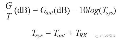

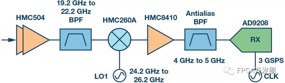
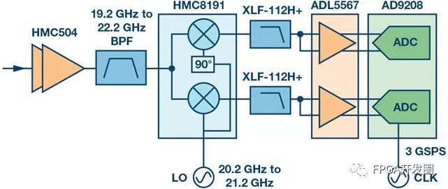
High IF (with integrated TRx) High IF (with GSPS ADC) Direct conversion Transceiver chip or data converter AD9371 AD9208 AD9208 (dual channel) Instantaneous bandwidth 100 MHz 1 GHz 2 GHz NF (dB) 2.5 2.3 2.3 IIP3 (dBm) -19 -20 -20 Maximum Pin (dBm) -38 -40 -41 Other spurious (HD2, HD3, MxN) 65 dB 73 dB 45 dB Image rejection (dBc) 75 80 25 Filtering difficulty low in low Power (W) 2.9 4.1 6.1 Power/GHz (W/GHz) 29 4.1 3.05 Package size (mm2) 300 510 580