STM32F407 bus storage framework and application design
Someone has asked the following questions on the STMCU community website:
Due to the experimental needs, the two DMAs of STM32F407 are used and triggered by the timer. During use, it is found that DMA1 cannot transfer the IDR data of GPIO to the memory. The DMA1 data stream transmission error flag appears during debugging, but there is no problem using DMA2 . . In addition, when the IDR of the access GPIO is changed to the ARR of the tim5 under the APB1, the DMA1 can also work normally. May I ask how is this going?
The consultant mentioned DMA1 and DMA in the STM32F4 series and two other peripherals, GPIO and TIM5. In order to clarify this problem, we need to look at the bus and storage framework of the STM32F407. As shown below:
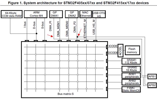
The whole system architecture consists of multiple layers of 32-bit AHB bus matrix and master-slave bus, and establishes interconnection access between each master and slave module. By means of the bus matrix, access from the master device to the slave device can be realized, and concurrent access and efficient operation of multiple high-speed peripherals can be realized. [It should be noted that for the STM32F4 series, the 64K CCM in the figure does not pass through the bus matrix and can only be accessed by the CPU. Natural DMA is unable to access it.]
Let's take a look at the access frame diagrams for DMA1 and DMA2 of STM32F407 . Both DMAs have dual AHB bus access ports, one for memory access and the other for peripheral access.

Combined with this DMA bus access block diagram and the above system memory bus frame diagram, it can be seen that the bus connections of the two DMA peripheral access ports are somewhat different.
The peripheral access port of DMA2 is connected to the bus matrix. It can access the AHB peripheral through the matrix and connect to the AHB-APB bridge 2 to further access the APB2 peripheral. The DMA1 is not connected to the bus matrix, just with the AHB-APB. Bridge 1 is connected to access the APB1 peripheral. [ Rectangle box represents bus matrix ]
The problem now is that DMA1 can't access GPIO, but it can be changed to TIM5. We can go to the Device overview section of the chip data sheet to view the relevant bus and peripheral link diagrams. The sections that intercept the STM32F40x block diagram are as follows:
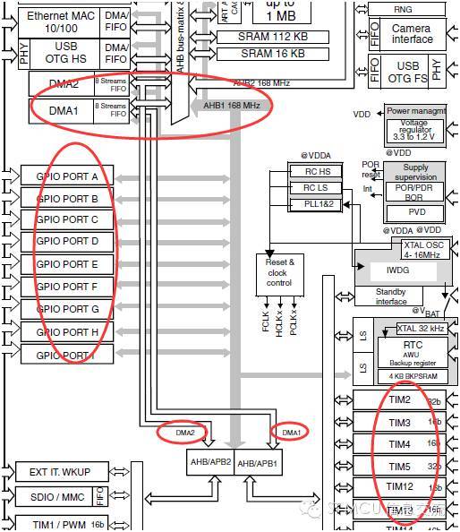
It is not difficult to see that the GPIO peripheral is connected to AHB1; TIM5 is connected to APB1. We can see clearly with the intermediate DMA access block diagram. The peripheral port of DMA1 is not connected to AHB1 at all, and naturally it is impossible to access the corresponding peripherals, such as GPIO. DMA2 can, because it can go through the bus matrix and then access the AHB1 peripherals. Why DMA1 can access TIM5 is not difficult to explain. Because AH1 peripheral port bus of DMA1 passes through AHB/APB1 bridge, it can access various peripherals of APB1, and TIM5 is one of the peripherals hanging on APB1 bus.
The consultant's question basically depends on the above figures to get the answer. These diagrams are important, and many of the information is also visually straightforward. The illustrations in the technical manuals are often very different, and don't turn a blind eye. All of the above mentioned are based on the bus architecture of the STM32F4 series. You can also look at the other series of system bus block diagrams. I believe you will find and gain something else.
Absolute rotary Encoder measure actual position by generating unique digital codes or bits (instead of pulses) that represent the encoder`s actual position. Single turn absolute encoders output codes that are repeated every full revolution and do not output data to indicate how many revolutions have been made. Multi-turn absolute encoders output a unique code for each shaft position through every rotation, up to 4096 revolutions. Unlike incremental encoders, absolute encoders will retain correct position even if power fails without homing at startup.
Absolute Encoder,Through Hollow Encoder,Absolute Encoder 13 Bit,14 Bit Optical Rotary Encoder
Jilin Lander Intelligent Technology Co., Ltd , https://www.jilinlandermotor.com