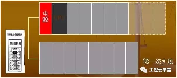
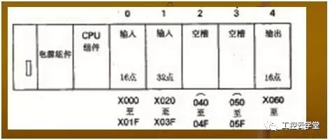
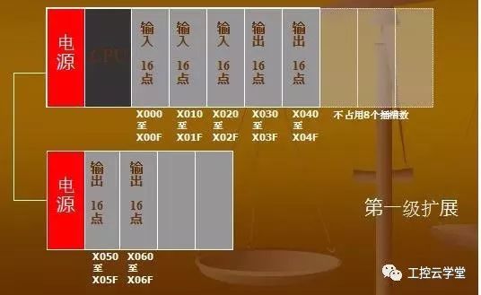
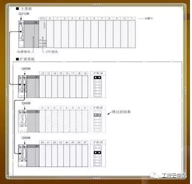
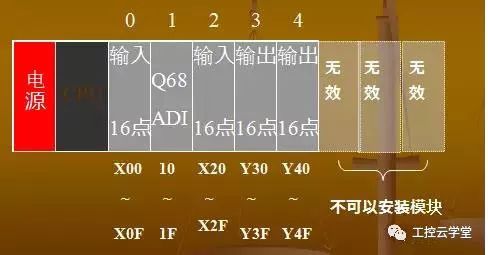
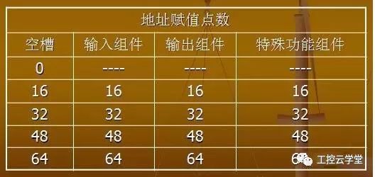
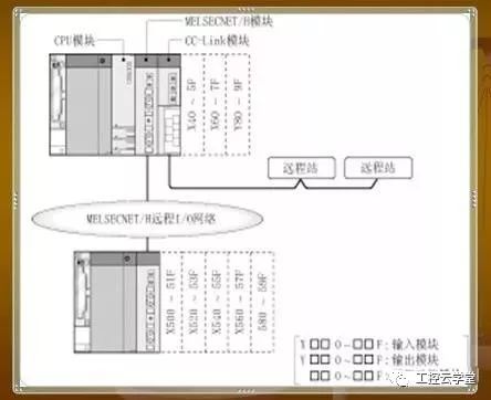
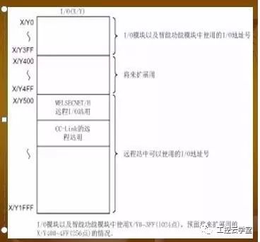
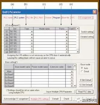
Q series PLC has the following features * Modular structure, easy to install. * Various types of input and output modules and special function modules are available to facilitate user configuration and expansion of the system. * Abundant basic instructions and application instructions, simple user programming. * Can use instruction table, ladder diagram, SFC, ST and other programming methods. There are two methods for assigning I/O addresses for Q series PLCs. 1) The CPU automatically assigns addresses to I/O. 2) Assigns I/O addresses to external devices. CPU automatically assigns I/O addresses CPU automatically assigns I/O addresses When the PLC is powered on or reset, it automatically performs an I/O address assignment check. 1. The assignment of the I/O address is continuously assigned to the right from the No. 0 slot on the main base unit. The input component is X□□□ and the output component is Y□□□. 2. When using an extension board, the first address of the first extension board follows the last address of the main board, and the address assignment of the extension board is irrelevant to the connection order of the cables, depending on the setting of the connector on the extension board. Expansion baseboard grade number. 3. The number of I/O points occupied by each component is equal to the number of I/O points of the component itself. There are no empty slots for I/O components or special function components. The number of I/O points occupied is 16 points. 4. When assigning I/O addresses, various main boards and extension boards are processed according to the actual number of slots. 5. If the level of the extension board is set to be discontinuous (level jumps are set), the number of I/O points occupied by these skipped extension levels is equal to 0, and the number of empty slots is not increased. 6. When setting the same number of expansion stages: It is not possible to use the same number of expansion stages in multiple extension boards. Assigning an I/O Address with an External Device Assigning an I/O address to an external device has a higher priority than the actual I/O module. Address assignment of I/O components and special function components can be controlled by an external device, ignoring address assignments based on the slot number and the number of I/O points of the component. Available Software (GPPW) If there is a mismatch between the number of set slots and the number of slots on the base board in use, the following conditions will occur: 1) When the number of slots set is larger than the number of slots of the board in use, the number of slots set will be occupied. The portion having more slots than the substrate in use becomes an empty slot. 2) When the set number of slots is less than the number of slots of the board in use: The slots after the set number of slots cannot be used. For example, if you use an 8-slot base, if you set 5 slots, the 3 slots on the right side of the baseboard will be prohibited. (Prohibited slots will cause an error if the module is installed (SP.UNIT LAY ERR). In order to facilitate the expansion of the system, a portion of the I/O addresses may be appropriately reserved when assigning I/O addresses, so that the system can insert non-16-point components. When non-16-point I/O components or special function components need to be repaired or replaced, the originally occupied I/O points should remain unchanged. The use of an external device to assign an I/O address to a slot has a higher priority than the number of I/O points actually inserted in the slot. 1) If the number of I/O points specified by a slot using an external device is less than the number of I/O points of the component it is actually plugged into, then the number of I/O points that the device can actually use should be reduced accordingly. 2) If the number of I/O points specified by a slot using an external device is greater than the number of I/O points for the component it is actually plugged into, then the excess number of points is treated as a dummy point. 3) If a slot is set to an empty slot by an external device, the I/O component inserted in the slot cannot be used. 4) For those slots that do not use external devices for I/O address assignment, the occupied I/O addresses are assigned according to the number of I/O points of the installed component. Note: 1) If the component to be inserted is a special function component, the I/O address assignment of the slot must be consistent with the actual I/O points occupied by the component. If they are inconsistent, an error will result. 2) When using the MELSECNET data communication system, the I/O addresses are allocated as follows: a) If the master station is assigned an I/O address, the master station and all remote I/O stations need to perform I/O address assignment. b) If an I/O address is assigned to a local station, then only the local station needs to be assigned an I/O address. c) If I/O address assignments are made to a combined I/O assembly, I/O address assignments should be made according to the output assembly assignment specification. Remote station I/O address number In a remote I/O system such as the MELSECNET/H remote I/O network, CC-Link, etc., input (X), output (Y) of the CPU module device can be performed to the I/O module/intelligent function module of the remote station. Distribution and control. In addition, input (X) and output (Y) can be used to refresh the link I/O (LX LY) of the MELSECNET/H module (device on the CPU module side). (1) I/O address number of the CPU module that can be used by the remote station When the input (X) and output (Y) of the CPU module are used for the I/O address number of the remote station, do not use the CPU-side I/O module. And the I/O address number being used by the intelligent function module can only be assigned using the number following it. For example, when X/Y0~X/Y3FF (1024 points) is used in the I/O module and intelligent function module on the CPU side, it can be used after the X/Y400 in the remote station. (2) Precautions when using remote station's I/O address number (a) Consider the setting of future expansion. Input (X) and output (Y) of the CPU module are used for the I/O address number of the remote station. Please consider the I/O module and intelligence of the CPU module side during the setting. Extension of functional modules. (b) When using MELSECNET/H and CC-Link, do not set the I/O address number of the refresh target (CPU module side device) of MELSECNET/H and the I/O of the CC-Link remote I/O system repeatedly. Address number. (c) About the number of I/O devices of the CPU module The number of I/O device points differs for each CPU module. I/O allocation by GX Developer (1) I/O assignment setting I/O assignment is performed in the setting of the I/O assignment of PLC parameters. (a) Slot Indicates the slot number and the number of slots of the baseboard. When the board is set in the automatic mode, the level of the board becomes "*", and the number of slots becomes the number of slots starting at the 0th slot of the main board. (b) Type (used in the CPU module) Select the type of mounting module in the following items. • Idle (empty slot) • Input (input module) • High-speed input (high-speed input module) • Output (output module) • I/O mixing (I/O mixing module) • Smart (intelligent function module) • Interrupt (interrupt) Module) The type of slot that is not set will be treated as the type of module installed. (c) Model name The model name of the installation module is set to be less than the half-width 16-character word. The set model name is not used in the CPU module. (only as a user's record) (d) Points (used in the CPU module) When changing the number of I/O points for each slot, select the number of points as described below. · 0 (0 points) · 16 (16 points) · 32 (32 points) · 48 (48 points) · 64 (64 points) · 128 (128 points) · 256 (256 points) · 512 (512 points) · 1024 (1024 points) Slots without a set point are counted as the number of installed modules. (e) Start XY (used in CPU module) When changing the I/O address number of each slot, set the changed start I/O address number. There is no continuous I/O address number after the slot where the start XY will be assigned to the set slot. The AC power meters are applicable to the measurement of single-phase or three-phase Ac Power Meter,Led 3 Phase Current Panel Meter,Ac Digital Electric Power Meter,Ac Multifunction Meter Jiangsu Sfere Electric Co., Ltd , https://www.elecnova-global.com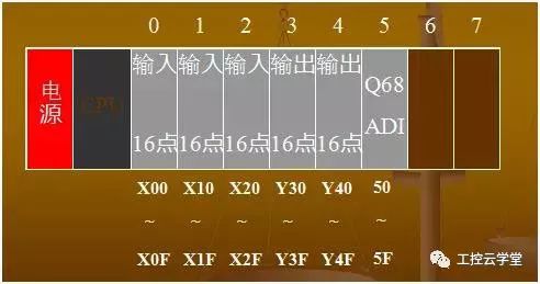


voltage and current parameters of distribution system. The transformation ratio of this series of meters is programmable. They supports digital input, relay output, analog output and communication functions. They provide a variety of different installation sizes and can directly replace the analog pointer ammeter.