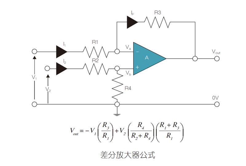
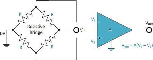
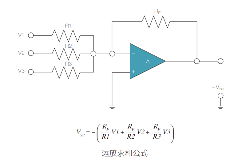
Some ideal op amp configurations assume that the feedback resistors are perfectly matched. In practice, the non-ideality of resistors can affect various circuit parameters such as common mode rejection ratio (CMRR), harmonic distortion, and stability. Single-chip IC designs for power solutions often have the ability to accurately match internal components. A carefully matched resistor network can achieve a more accurate match order of magnitude than mismatched discrete components. The digital signal transmitted through the high-precision matching resistor also makes the noise and distortion of the output analog signal smaller. Some ideal op amps (often abbreviated as op-amp or opamp) configurations assume that the feedback resistors exhibit a perfect match. However, in practice, the non-ideal characteristics of the resistor affect various circuit parameters such as common mode rejection ratio (CMRR), harmonic distortion, and stability. An op amp is a dc-coupled, high-gain electronic voltage amplifier with a differential input and is typically a single-ended output. In this configuration, the output potential produced by the op amp (relative to the circuit ground) is typically thousands of times greater than the potential difference between its inputs. The actual performance of precision amplifiers and analog-to-digital converters (ADCs) is often difficult to implement because the datasheet specifications are based on ideal components. Carefully matched resistor networks are orders of magnitude higher than mismatched discrete components, ensuring that datasheet specifications meet precision integrated circuit (IC) requirements. In the monolithic IC design of the power scheme, we often use the ability to accurately match internal components. For example, a low offset voltage is provided by precisely matching the input transistors of the op amp. If we have to use discrete transistors to make an op amp, there will be an offset voltage of 30mV or higher. This ability to accurately match components includes on-chip resistor matching. Figure 1: Inverting op amp configuration. The integrated differential amplifier utilizes precise on-chip resistor matching and laser trimming. The excellent common mode rejection of these integrated devices relies on the precise matching and temperature tracking of well-designed integrated circuits. Significant tracking gain can be achieved by using a pair of cut (1:1 ratio) chips and placing them in a closed network package. The ultimate gain can be achieved by using ultra-high precision resistors (thermistor or cold junction temperature coefficient of resistance is 0.05 ppm/oC and the adjacent two chips show a temperature drift trajectory difference of 0.1 ppm/oC). For best tracking results, a very low absolute temperature coefficient of resistance (called ultra-high precision resistors) must be used, which also helps to avoid the complexity due to temperature gradients. Matching resistors are critical to the performance of many differential circuits. Any mismatch between the ratios will result in common mode errors. Among these circuits, CMRR is an important indicator because it indicates how many undesired common-mode signals will appear in the output. The CMRR caused by the resistance in these circuits can be calculated using the following formula: CMRR=1/2(G+1)/ Δ R/R (G = gain [magnification factor], R = resistance [Ω]) In precision medical devices such as scanning electron microscopes, blood cell counting devices, and in vivo diagnostic probes, the use of differential amplifiers with highly matched precision resistors is critical. Figure 2: Differential amplifier. Wheatstone bridge (or resistive bridge) circuits can be used in a variety of applications. Today, with modern op amps, we can use a Wheatstone bridge circuit to connect various frequency converters and sensors to these amplifier circuits. In addition to comparing unknown resistances to known resistances, Wheatstone bridges have many uses in electronic circuits. The Wheatstone bridge circuit is actually a combination of two simple resistors in series and parallel. When the resistance between the voltage source and the ground is balanced, a zero voltage difference will occur between the two parallel branches. The Wheatstone bridge circuit has two inputs and two outputs, consisting of four resistors, as shown in the diamond structure of Figure 3. This is a typical drawing of the Wheatstone Bridge. When used with an op amp, the Wheatstone bridge circuit can be used to measure and amplify small changes in resistance. The use of ultra-high precision resistors accurately grounds the bridge balance point compared to the use of conventional thin film resistors. All four resistors perform their duties, so their matching and stability are necessary for bridge balancing. Figure 3: Wheatstone bridge differential amplifier. A well-balanced Wheatstone bridge differential amplifier can be used for smart grid power circuit measurements in power stations. They are also used in solar energy converters where the efficiency of the converter is directly dependent on the balance of the resistance bridge using high stability resistors. Precision and low noise op amps are typically used to condition sensor signals (such as temperature, pressure, light) before they enter the ADC. In this application, the two specific op amp parameters, input offset voltage and input voltage noise, are critical for good system resolution. The ultra-high precision resistor's low offset and low noise parameters make it ideal for sensor interfaces and transmitters. Figure 4: The operational summation formula. Figure 5: Digital to Analog Converter. For reference, high precision resistors for digital to analog converter (DAC) inputs can also achieve better results. The digital signal transmitted by the high-precision matching resistor makes the noise and distortion of the analog signal output smaller. The noise level of Bulk Metal Foil technology is -40dB, making this resistor technology an ideal solution for reference and gain resistors in high-end audio ADC/DAC circuits. Low-noise operation is also critical in avionics, military and aerospace (AMS) RFI equipment, including gyroscopes, GPS chipset control amplifiers, and antenna direction control units.
Tablet speaker:
Tablet speaker is a kind of micro speaker unit which uses a diaphragm made of Mylar material. Mylar speakers are of ultrathin design and lightweight and clear voice. It is widely used mobile internet devices (tablet, notebook-).
There are two types of Mylar speakers from the shapes:
1) Round shapes, we have products from 10mm to 57mm in diameter.
2) Oblong shape, we have products in sizes of 1510/1712/1813-..
FAQ
Q1. What is the MOQ? Tablet Speaker,Notebook Speaker,Laptop Speaker,Laptop Table Speaker Shenzhen Xuanda Electronics Co., Ltd. , https://www.xdecspeaker.com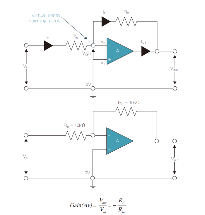


XDEC: 2000pcs for one model.
Q2. What is the delivery lead time?
XDEC: 15 days for normal orders, 10 days for urgent orders.
Q3. What are the payment methods?
XDEC: T/T, PayPal, Western Union, Money Gram.
Q4. Can you offer samples for testing?
XDEC: Yes, we offer free samples.
Q5. How soon can you send samples?
XDEC: We can send samples in 3-5 days.