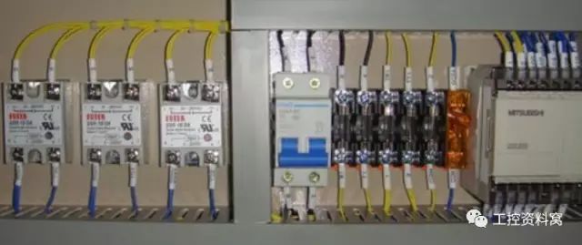
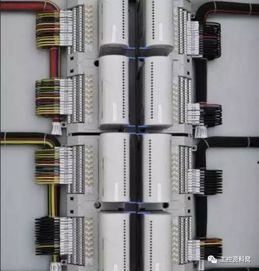
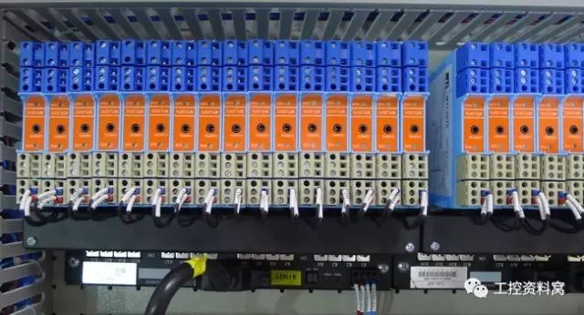
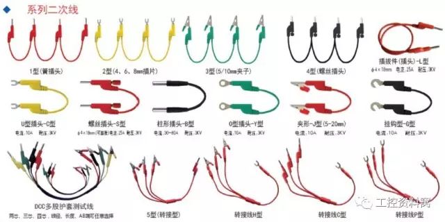
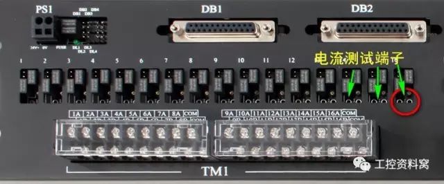
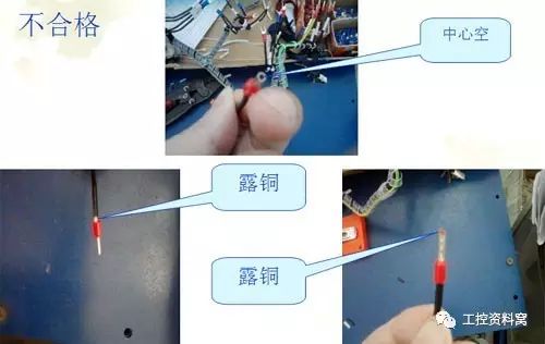
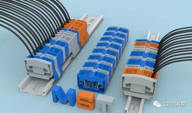
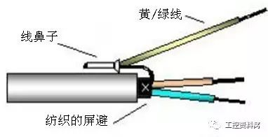
After entering the 1990s, the electronic control equipment industry has developed rapidly especially in recent years, and new products have emerged one after another. The products not only have made great progress in performance, structure and other aspects, but also have higher and higher requirements in terms of appearance. They are developing in the direction of furniture and decoration. The secondary circuit is an essential part of any electrical equipment. The electrical performance of the secondary circuit directly affects the performance, reliability and safety of the entire electrical equipment. At the same time, the secondary components of the assembly, marking, wire selection, laying and arrangement and combination of other items, constitute the secondary circuit wiring process of the important content. The level of secondary wiring technology will have a direct impact on product quality. In the past, enterprises only paid attention to the structural design of products and the improvement of electrical performance, and neglected the secondary wiring work, resulting in the backwardness of the secondary circuit wiring technology and outdated methods. Under the new situation, the original secondary wiring technology is far from being able to adapt to the needs of new product development and market development. Therefore, the adoption of new processes, new technologies, and the use of suitable new types of electrical accessories have become very urgent issues. 01 According to the figure construction, connection is correct. 02 The connection of the secondary wire (including bolting, plugging, welding, etc.) should be solid and reliable. The wire harness should be horizontal and vertical, and the configuration should be firm, distinct, and neat and beautiful. The installation position and wiring method of the control cabinet components of the same model and specification of the same contract shall be the same. 03 When using wire harness wiring, the fixed wire harness should be horizontally and vertically arranged and should be bundled and fixed. The bundling distance should not be greater than 100mm, the horizontal wire bundle fixed spacing should not be greater than 300mm, and the vertical wire bundle fixed spacing should not be greater than 400mm. 04 The line numbers of the devices in the same column are as consistent as possible. The conventions are from left to right, from bottom to top and from inside to outside. 05 Secondary line cross-sectional area requirements: Single wire not less than 1.5mm2 Multi-strand wire is not less than 1.0mm2 Weak circuit is not less than 0.5mm2 Current loop is not less than 2.5mm2 Protective ground wire is not less than 2.5mm2 06 There should be no connector in the middle of all secondary circuit connecting wires. The connector can only be located on the terminal block or terminal block of the device. 07 The connection of each electrical component is allowed up to 2 wires. The connection points of each terminal are generally not suitable for connecting two wires. In special cases, if two wires must be connected, the connection must be reliable. 08 The secondary wire should be far away from the arcing elements (circuit breakers, contactors, etc.) and must not interfere with the electrical operation. 09 The connection between the ammeter and the shunt must not pass through the terminal, and its length must not exceed 3 meters. 10 The current loop should be connected to the measuring instrument through a test terminal (the function can be directly measured without disconnecting the wire). 11 Multi-strand wire ends should be added cold-pressed end wire. Single conductors with a cross-sectional area of ​​less than 1 mm2 in a weak current circuit shall be soldered or other suitable means of wiring. 12 The secondary wire must not pass between the busbars. 13 Pull-type spring terminal connection: 1) Stripping length of hard wire: about 10 mm. 2) The soft wire should be put on the wire and the nose should be pressed tightly before inserting it into the terminal. Note that the copper wire core should not be exposed on the wire nose and should be compacted. 3) Acceptable crimping. 4) Failed 5) Insert the wire into the terminal port until it feels that the wire has been inserted into the bottom and the top is not exposed to copper. 14 Shielded cable connection. ◠Tighten the shield wire to approximately 15 mm length; ◠Use the wire nose to press the wire and the shield together; ◠The pressed wire is folded back on the outer layer of the insulated wire; ◠The shield wire is single-ended grounded. 15 Secure the wire connection with the heat-shrink tube. Top Plug,Top Plug In,Standard Power Conversion Plug,Power Conversion Plug WENZHOU TENGCAI ELECTRIC CO.,LTD , https://www.tengcaielectric.com