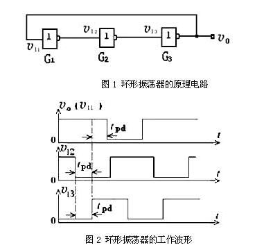
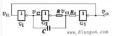
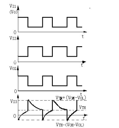
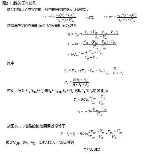
A ring oscillator consists of three non-gates or more odd-numbered non-gate outputs connected end to end to form a ring-shaped machine. Taking three non-gates as an example, the non-gate A output is connected to the non-gate B input, the non-gate B output is connected to the non-gate C input, and the non-gate C output is connected to the non-gate A input. The output signal can be derived from any connected location. The ring oscillator is formed by connecting the odd-numbered inverters end-to-end with the inherent propagation delay time of the gate circuit. The circuit has no steady state. Because in the static (assuming no oscillation), the input and output of any inverter can not be stable at high level or low level, only between high and low levels, and in the amplified state. Assume that for some reason v11 produces a small positive transition, after G1's transmission delay time tpd, v12 produces a larger amplitude negative transition, making the v13 larger after the G2 transmission delay time tpd. The positive transition, after G3 transmission delay time tpd, produces a larger negative transition at vo and feeds back to the G1 input. It can be seen that after 3tpd, v11 automatically jumps to low level, and after 3tpd, v11 will jump to high level. As a result of this cycle, self-excited oscillations occur. As shown in Figure 2, the oscillation period is T=6tpd. As shown in Fig. 1, in order to further increase the transmission delay time of RC and G2, the ground terminal of the capacitor C is changed to the output terminal of G1 in the practical circuit. as shown in picture 2. For example, when a negative transition occurs at v12, v13 first jumps to a negative level through capacitor C, and then charges capacitor C from this negative level, which lengthens the time from v13 starting to charging to rising to VTH. It is equal to increasing the transmission delay time from v12 to v13. Figure 4 Practical improvement circuit diagram of the ring oscillator Usually, the delay time generated by the RC circuit is much larger than the transmission delay time of the gate circuit itself, so the calculation of the oscillation period can only ignore the effect of the RC circuit and neglect the inherent transmission delay time of the gate circuit. In addition, in order to prevent the current flowing through the clamp diode of the input terminal of the inverter G3 when the negative transition of v13 occurs, the protection resistor RS is connected in series at the G3 input terminal. The voltage waveform at each point in the circuit is shown in Figure 2. The formula T≈2.2RC can be used to approximate the oscillation period. However, it should be noted that the assumptions of its assumptions are met, otherwise the calculation results will have a large error. This kind of oscillator is characterized by simple circuit and easy starting. If there is no delay network, no RC components are needed, which is easy to integrate. The disadvantage is that there is no delay in network frequency, which is not convenient and flexible. To achieve low frequency oscillation, many non-gates are needed. Therefore, it is not easy to realize, and because the delay time of the gate circuit has a certain error, the frequency at the time of production is not accurate. If a RC network is added, the required chip area and cost are not dominant compared to a symmetric multivibrator or an asymmetric multivibrator that also requires a RC component. It is mainly used for low-frequency high-frequency oscillations integrated in integrated circuits, and simple oscillators in ordinary digital circuits. SHENZHEN CHONDEKUAI TECHNOLOGY CO.LTD , https://www.szsiheyi.com
Ring oscillator principle and application _ Practical circuit of ring oscillator
What is a ring oscillator?