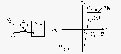
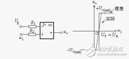
1. Voltage comparator A voltage comparator (comparator for short) is a circuit that compares an analog voltage signal with a reference voltage. (1) Zero-crossing comparator The zero-crossing voltage comparator is a typical amplitude comparison circuit. The circuit diagram and transmission characteristic curve of the in-phase zero-crossing voltage comparator are shown in FIG. (a) Circuit diagram (b) Voltage transmission characteristics Figure 1 Zero-crossing voltage comparator (2) Arbitrary voltage amplitude comparator The input terminal of the zero-crossing comparator is changed from ground to a fixed voltage value UR, and the voltage comparator is obtained. The circuit is shown in 2. Adjustment can easily change the threshold. (a) Circuit diagram (b) Voltage transmission characteristics Figure 2 In-phase arbitrary voltage comparator (3) Basic characteristics of the comparator Working in open loop or positive feedback state; the output of the comparator has only two stable states of high level and low level; non-linear.
Focusing on the development and production of Wireless Charging products that make life easier.
Supply various wireless charger including multifunctional Wireless Charger, Car Wireless Charger, Magnetic Wireless Chargin, Wireless Charging Mouse Pad, etc.
We help 200+ customers create custom wireless charging products design for various industries.
Manufacturing high quality products for customers according to international standards, such as CE ROHS FCC REACH UL SGS BQB etc.
Wireless Charging Pad,Wireless Phone Charger,Wireless Car Charger,Bluetooth Charger TOPNOTCH INTERNATIONAL GROUP LIMITED , https://www.mic11.com