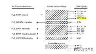
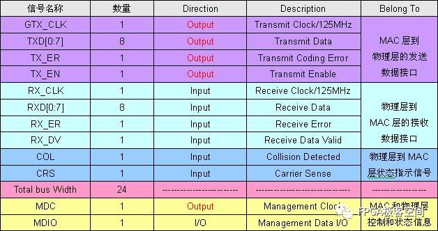
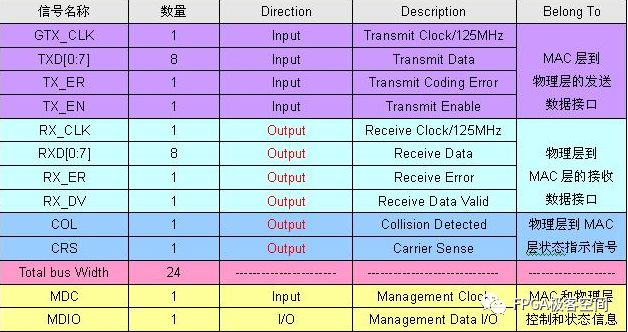
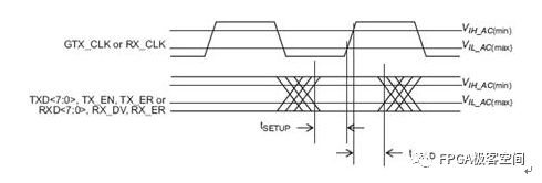
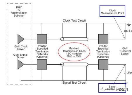
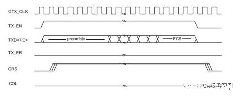
The GMII interface provides an 8-bit data channel with a 125MHz clock rate and a data rate of 1000Mbps. The following figure defines the input and output signals of the RS layer and the signal of the STA: Reconciliation Sublayer (RS) and STA connectionsto GMII The following describes the signal definition and timing characteristics of the GMII interface in detail. Since the GMII interface has MAC and PHY modes, it will be analyzed based on these two different modes. GMII interface signal definition The GMII interface can be divided into a MAC mode and a PHY mode. Generally speaking, the MAC and the PHY are connected, but the MAC and the MAC are also connectable. In the GMII interface, it uses 8 data lines to transmit data, so when transmitting 1000M data, the clock will be 125MHz. The GMII interface mainly includes four parts. One is the data transmission interface from the MAC layer to the physical layer, the second is the data interface from the physical layer to the MAC layer, the third is the status indication signal from the physical layer to the MAC layer, and the fourth is the transmission control between the MAC layer and the physical layer. MDIO interface with status information. The MAC mode definition of the GMII interface: Note that in the table, the signal GTX_CLK is the output signal for the MAC, which is inconsistent with the input characteristics of the TX_CLK in the MII interface. GMII interface PHY mode definition: Note that in the table, the signal GTX_CLK is the Input signal for the PHY, which is inconsistent with the TX_CLK output characteristic in the MII interface. GMII interface timing characteristics In the GMII interface, the TX channel reference clock is GTX_CLK, and the RX channel reference clock is RX_CLK, and 802.3-2005 defines the relationship between them. GMII signal timing at receiver input From the above figure, Spec only defines the setup time and hold time of the receive side in the TX and RX channels. Obviously, the Spec only defines the reception characteristics on the PHY side of the TX channel, and there is no definition of the transmission characteristics on the MAC side of the TX channel. The ICVendor can make appropriate adjustments to the transmission characteristics of the MAC on the side of the TX channel as long as the final timing meets the reception characteristics of the PHY side of the TX channel. In the same way, the Spec only defines the reception characteristics of the MAC side of the RX channel, and there is no definition of the transmission characteristics on the RX side of the RX channel. The IC Vendor can make appropriate adjustments to the transmission characteristics of the PHY on the side of the RX channel as long as the final timing meets the reception characteristics of the MAC side of the RX channel. Setup and Hold Time values As you can see from the figure, there are two sets of setup and hold times. The first group of Specs is defined according to the test circuit given in the following figure, that is, the Spec does not consider the influence of the transmission line mismatch on the PCB. The second set of Spec defines the time requirement of receiver at its inputpins. It takes into account the effects of mismatched transmission lines on the PCB. General IC Vendors need to design their ICs according to the second set of Specs. GMII Interface Setup and Hold Time Test Circuits GMII signal functional characteristics: <1>: GTX_CLK (transmit clock), GTX_CLK (Transmit Clock) is a continuous clock signal (that is, the system starts, the signal is always present), it is TX_EN, TXD, and TX_ER (signal direction is from RS to PHY) The reference clock is sampled at the rising edge of the signal on the PHY side and GTX_CLK is driven by the MAC. The clock frequency of GTX_CLK is 12.5 of the data transmission rate, namely 125MHz. <2>: For the same RX_CLK, it has the same requirements as TX_CLK, except that it is the reference clock for RX_DV, RXD, and RX_ER (the signal direction is from PHY to RS), and the MAC is sampled at the rising edge of the clock. . RX_CLK is driven by the PHY. The PHY may extract the clock RX_CLK from the received data, or it may drive the RX_CLK from a nominal reference clock (eg, the TX_CLK reference). <3>: GMII interface transmission timing, receiving timing as shown below, as to the other signal's functional characteristics and in the data transmission process, the logic of different signal changes represent the meaning, not described here, in general and "MII signal function Similar to the description in the section "Features", the reader can refer to the Spec of 802.3-3005. GMII signal transmission timing GMII signal reception timing Randm Vape,Randm Tornado Vape,China Randm Tornado Vape,Randm Tornado Disposable,Randm Disposable Vape Manufacturer Nanning Nuoxin Technology Co., LTD , https://www.nx-vapes.com