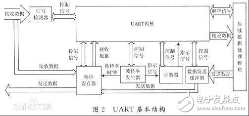
The UART is a general purpose serial data bus for asynchronous communication. The bus bidirectional communication enables full duplex transmission and reception. In embedded design, the UART is used to communicate between the host and the auxiliary device, such as communication between the car audio and the external AP, and communication with the PC includes communication with the monitor debugger and other devices such as EEPROM. Parallel data is used inside the computer. It is not possible to send data directly to the modem. It must be UART-organized for asynchronous transmission. The process is: the CPU first puts the data to be written to the serial device into the UART register (temporary memory block). It is then transmitted to the serial device via FIFO (First Input First Output). If there is no FIFO, the information will become messy and cannot be transferred to the modem. It is a chip for controlling computers and serial devices. One thing to note is that it provides an RS-232C data terminal device interface so that the computer can communicate with a modem or other serial device that uses the RS-232C interface. As part of the interface, the UART also provides the ability to convert parallel data transferred from within the computer into an output serial data stream. Serial data from outside the computer is converted to bytes for use by devices with parallel data within the computer. A parity bit is added to the output serial data stream, and a parity is received for the data stream received from the outside. A start and stop flag is added to the output data stream, and the start and stop flag is deleted from the received data stream. Handles interrupt signals from the keyboard or mouse (the keyboard and mouse are also serial devices). It can handle the synchronization management of computers and external serial devices. Some of the more advanced UARTs also provide buffers for input and output data. The newer UART is the 16550, which stores 16 bytes of data in its buffer before the computer needs to process the data. The usual UART is 8250. If you buy a built-in modem, there will usually be a 16550 UART inside the modem. 1. An output buffer register that receives parallel data sent by the CPU from the data bus and saves it. 2. An output shift register that receives parallel data sent from the output buffer and shifts the data out at a rate of the transmitted clock, ie, converts the parallel data into serial data output. 3. Input shift register, which shifts the data appearing on the serial data input line at the rate of receiving the clock. When the data is full, it is sent to the input buffer register in parallel, that is, the serial data is converted into parallel data. 4, the input buffer register, which receives parallel data from the input shift register, and then taken away by the CPU 5. The control register receives the control word sent by the CPU, and determines the transmission mode and data format of the communication by the content of the control word. For example, whether it is asynchronous or synchronous, the number of bits of data characters, whether there is parity, whether it is odd or even parity, the number of bits of the stop bit, etc. 6, the status register. The status register stores various status information of the interface, such as whether the output buffer is empty, whether the input characters are ready, and so on. During communication, when a certain state is met, the state detection logic in the interface sets the corresponding position of the status register to "1" for the CPU to query. Usb Docking Station,Usb Hub Docking Station,Docking Station With Hdmi,Usb C Hub Laptop Docking Station Shenzhen GuanChen Electronics Co., Ltd. , https://www.gcneotech.com