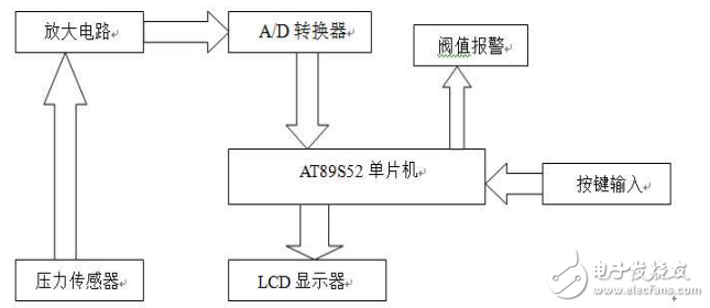
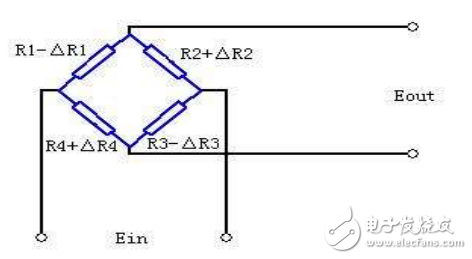
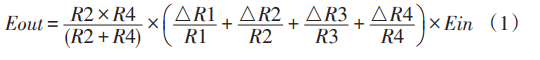
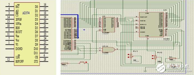
According to the application situation of current electronic scales, this paper analyzes a simple electronic scale device by using single chip microcomputer and AD574. Based on the analysis and measurement principle, a simple 51 series single chip microcomputer is selected as the main control system, and the sensor circuit is designed according to the measurement requirements. , AD conversion circuit, over-range alarm circuit, display circuit, button circuit, etc., according to the hardware circuit, completed the corresponding software design. The electronic scale generally consists of three parts, the load cell, the load-bearing system, and the force-return system. On this basis, it is divided into other hardware circuit sub-units, such as single-chip microcomputer minimum system circuit, sensor circuit, AD conversion circuit, over-range alarm circuit, display circuit, button circuit, storage circuit and so on. The measuring principle is: when the object is placed on the weighing platform of the load-bearing system, its weight parameter will be generated by the sensor to generate a pressure-electric effect, converted into an electrical signal corresponding to its weight, and then the electrical signal is amplified and passed through the amplifying circuit. AD processing, and finally the signal is input to the MCU processing, after the MCU processing, the input information is displayed on the LCD. The accuracy of the measurement is generally determined by the load cell. According to its measurement principle, the overall hardware block diagram of the design is shown in Figure 1. It mainly includes pressure sensor circuit module, amplification circuit module, AD conversion module, LCD display module, threshold alarm module, and single-chip control system module. Figure 1 hardware block diagram The design adopts SP20C-G501 ​​resistance strain sensor. The load cell is composed of combined S-beam structure and metal foil strain gauge, and has overload protection device. In the process design, the Wheatstone bridge is used for voltage acquisition and conversion. It can suppress the influence of temperature change, suppress the interference ability, and the compensation is convenient and simple. Therefore, the selected sensor has high precision, small zero drift and stable operation. The sensor schematic is shown in Figure 2: Figure 2 sensor working principle diagram How it works: When measuring with a strain gauge, attach it to the elastomer. When the elastic body is deformed by force, the sensitive grid of the strain gauge is also deformed, and the resistance value changes correspondingly, and is converted into a voltage or current change by the conversion circuit. Since the internal circuit uses Huygens bridge, when the elastic body is subjected to load deformation, the output signal voltage can be given by the following formula (1): The AD574 is a 12-bit single-chip A/D converter manufactured by Analog Devices, USA. It adopts a successive approximation A/D converter with a maximum conversion time of 25us and a conversion accuracy of 0.05%, so it is suitable for high-precision fast conversion sampling systems. The chip contains microprocessor interface logic (with three-state output buffer), so it can be directly connected to various types of 8-bit or 16-bit microprocessors without the need for additional logic interface circuits. It can be compatible with CMOS and TTL circuits. . The AD574 is available in a 28-pin dual in-line standard package. Figure 3 AD574 chip and wiring diagram with AT89s52
Resistive Touch Screen
The outermost layer of resistance screens is usually a soft screen that connects the internal contacts up and down by pressing. The inner layer contains the oxidized metal of the physical material, namely N-type oxide semiconductor (indium oxide), also known as indium oxide, with an optical transmittance of 80% and the upper and lower layers separated by the middle. ITO is the main material used in both resistive and capacitive touch screens. Their working surface is the ITO coating. The outer layer is pressed by fingertips or any object to make the surface film concave and deformed. According to the leading line number of screen, divide again have 4 line, 5 line and much line, threshold is low, cost is opposite cheap, advantage is not affected by dust, temperature, humidity. Disadvantages are also obvious, the outer screen film is easy to scratch, can not use sharp objects to touch the surface. In general, multi-touch control is not allowed, that is, it can only support a single point. If two or more contacts are pressed at the same time, they cannot be recognized and accurate coordinates can be found. To enlarge a picture on the resistance screen, you can only click "+" several times to make the picture be enlarged step by step. This is the basic technical principle of the resistance screen.
Control by pressure induction. When a finger touches the screen, the two conductive layers are in contact at the touch point and the resistance changes. A signal is generated in both X and Y directions and transmitted to the touch screen controller. The controller detects the contact and calculates the position of (X, Y), then works according to the simulated mouse mode. Resistive touch screen is not afraid of dust, water and dirt, and can work in harsh environments. But because the outer layer of the composite film is made of plastic material, its anti-explosion property is poor, and its service life is affected to some extent.
The resistive touch screen is controlled by pressure induction. The surface layer is a layer of plastic and the bottom layer is a layer of glass, which can withstand the interference of harsh environmental factors. However, it has poor hand feel and light transmittance, so it is suitable for wearing gloves and occasions that cannot be touched directly by hand.
Resistive Touchscreen,Resistive Screen,Resistive Touch,Resistive Touch Panel Tonya Display Limited , https://www.tydisplay.com