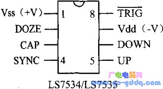
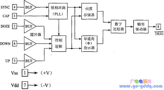
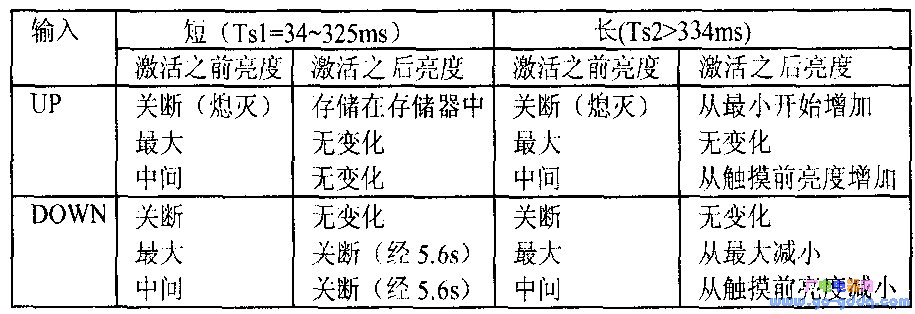
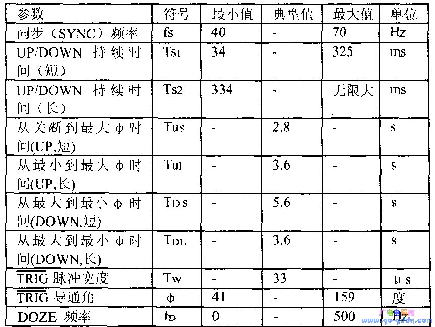
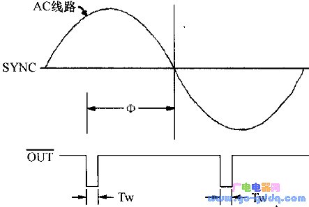
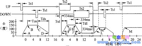
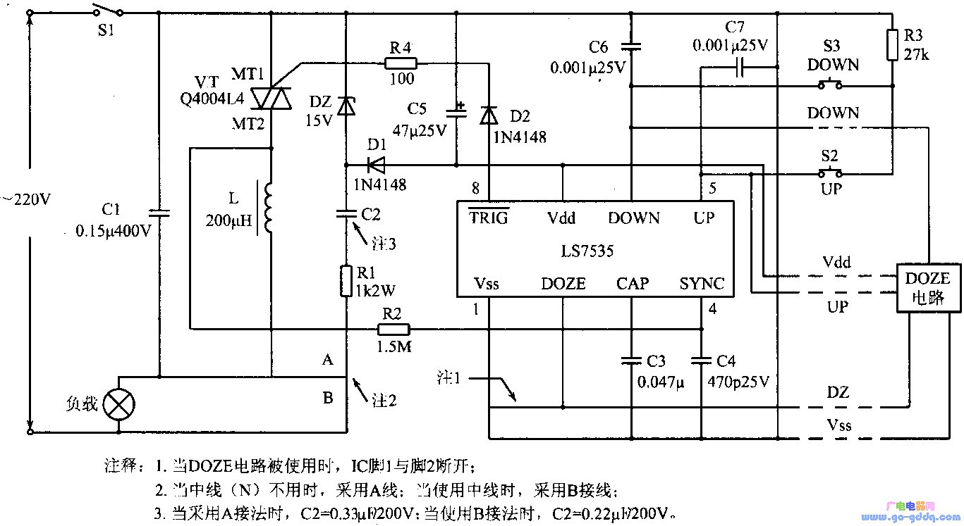
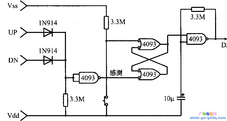
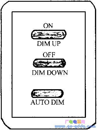
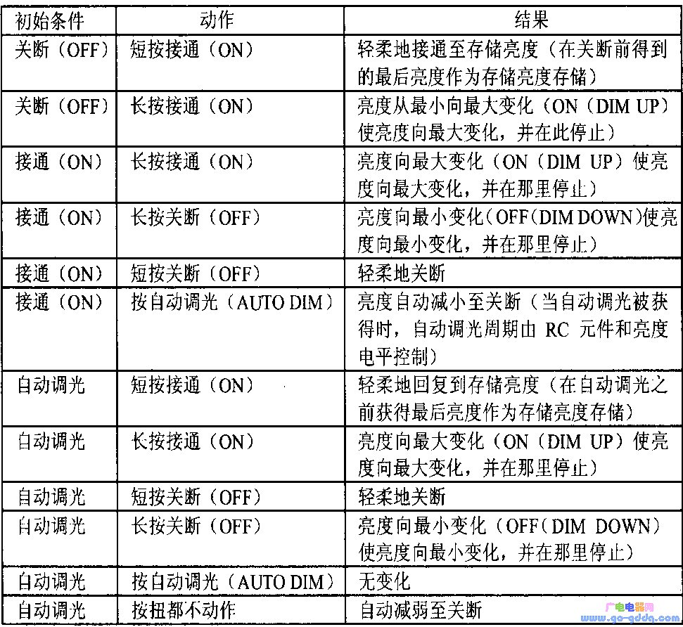
The LS7534 and LS7535 are incandescent brightness control MOs integrated circuits. The LS7534/LS7535 controls the brightness of the lamp by controlling the ignition (trigger) angle of the triac in series with the lamp. All internal timing is synchronized to the AC line frequency by means of a phase-locked loop (PLL). IC's duty cycle control range is 23% to 88%, the corresponding AC line half cycle conduction angle φ is 41 ° ~ 159 °, when the conduction angle is 159 °, the lamp brightness is the largest; the conduction angle is 41 ° The brightness of the lamp is minimal. The LS7534 uses a touch switch to control the brightness of the lamp, and the LS7535 uses a push button switch. Structure and pin function The LS7534/LS7535 are available in 8-pin DIP or SOlC packages (with s suffix) and are shown in the figure above. The figure below shows a block diagram of its internal structure. The pin functions are as follows: Vss (pin 1) is the positive power supply voltage input terminal, the range is 12~18V; DOZE (foot 2) is the clock input terminal, the brightness transitions with the negative direction of the clock, and the brightness is increased by the same amount. When the light is turned off, the input on this foot does not work. Activate the input on the uP pin to turn the light on again. This pin requires 83 clock pulses when the lamp is turned from maximum brightness to extinction. When the input on the uP or DOWN pin is activated, the DOZE input is invalid; CAP (pin 3) is a 0.047μF filter capacitor for the internal PLL; sYNc (pin 4) is the Ac line (50Hz/60Hz) sync input; The input of uP (pin 5) controls the conduction and the TRIG output conduction angle (φ). For the Ls7534, the logic low level is the active level. For the LS7535, the logic high level is the active level, and there is a pull-down resistor of about 500kΩ inside the UP pin. DOWN (pin 6) input control turns off the TRIG output. The corner angle; Vdd (pin 7) is the negative terminal of the power supply voltage; the output of TRIG (pin 8) provides a low level pulse and occurs in each half cycle of the sYNc signal. With the input on the UP or DOWN pin, the TIG output conduction angle can vary from 41° to 159°. working principle 1. Short activation (34 - 325ms) (1) uP input: When the light is turned off, if a short activation is applied to the uP (foot) input, the brightness of the light is gradually increased to the maximum value or the previous brightness information is stored in In memory. The elapsed time from lamp off to full conduction is 2.8s. When the lamp is illuminated at any brightness, the short activation pulse applied to the uP input has no effect. (2) I) OWN input: If a short activation is applied to the D0wN input, the brightness of the lamp gradually decreases until it is turned off. It takes 5.6 seconds for the lamp to be fully switched on and off. When the lamp is turned off, the short activation pulse applied to the DOWN input has no effect. 2. Long active (greater than 334ms) (1) uP input: If a long active is applied to the uP input, as long as the activation is maintained until full brightness is reached, the brightness of the light will gradually increase from before activation. At full brightness, any continuous long activation no longer works. (2) D0wN input: If a long activation is applied to the D0wN input, as long as the long activation is maintained until the minimum brightness is reached, the brightness of the lamp will gradually decrease. At the minimum brightness, any continuous long activation no longer works. The long activation applied to the D0wN input does not work when the light is turned off. The above table lists the relationship between the duration of the iP's uP and DOWN (foot) input signals and the brightness of the lamp. The following table lists the transient characteristics of Ic. The relationship between the output conduction angle book and the pulse width Tw is as shown below. The figure below shows the relationship between the output conduction angle and the IJP/D~) WN input. In the above figure, it should be noted that: (1) the polarity of the LS7534 and LS7535 UP/DOWN signals are opposite; (2) points A, D, E, and K correspond to =4l. Minimum brightness at the time, points B, C, G, and H correspond to the maximum brightness from: 159c', point M represents any intermediate brightness; (3) points F, J, and L correspond to small = 64c', from E to The interval between F or J to K is 934ms and the angle is 23. Application circuit The LS7534 is activated using the touch switch, while the LS7535 uses the push button switch. The figure above shows the dimming circuit composed of LS7535. Lamp brightness is set by uP and DOWN switch closure, R1, C2, Dz and C5 provide 15V for the chip, R2 and c4 for sYNc input AC signal filtering and current limiting, c3 for Ic internal PLL filtering, R3 for R3 Limit the current of the foot Vss and the uP and DOWN pins when the button switch is turned on, and Cl and L form the radio frequency interference (RFI) filter, R4 and. D2 is used to limit the current between the Ic output (TRIG) and the bidirectional thyristor (vT) gate. c6 and c7 are used to eliminate the coupling switching transient noise from the triac at the uP and DOWN inputs. When using the DOZE circuit, the circuit shown above can be used. The function of this circuit is to generate an O. A slow clock of 04 Hz is input to the DOZE pin of Ic. If the uP/DOWN input is not activated, the sense node of the DOZE circuit is at a logic high level. Pressing the DOZE switch momentarily will set the RS trigger to energize the oscillator. The falling edge of each clock on the DZ terminal reduces the brightness of the lamp until the light is extinguished. When the light is turned off, the oscillator in the dimmer circuit no longer functions. When the lamp is turned on again by activating the uP input, the RS flip-flop is reset and the clock on the Dz terminal is turned off. When using the DOZE circuit, the connection between Ic pin 1 and pin 2 should be broken. The wall switch with the Ls7535 is shown above. The starting conditions, actions and results are listed in the table below.
ZGAR Aurora 1800 Puffs
ZGAR electronic cigarette uses high-tech R&D, food grade disposable pod device and high-quality raw material. All package designs are Original IP. Our designer team is from Hong Kong. We have very high requirements for product quality, flavors taste and packaging design. The E-liquid is imported, materials are food grade, and assembly plant is medical-grade dust-free workshops.
Our products include disposable e-cigarettes, rechargeable e-cigarettes, rechargreable disposable vape pen, and various of flavors of cigarette cartridges. From 600puffs to 5000puffs, ZGAR bar Disposable offer high-tech R&D, E-cigarette improves battery capacity, We offer various of flavors and support customization. And printing designs can be customized. We have our own professional team and competitive quotations for any OEM or ODM works.
We supply OEM rechargeable disposable vape pen,OEM disposable electronic cigarette,ODM disposable vape pen,ODM disposable electronic cigarette,OEM/ODM vape pen e-cigarette,OEM/ODM atomizer device.
Aurora 1800 Puffs,Pod System Vape,Pos Systems Touch Screen,Empty Disposable Vape Pod System,1800Puffs Pod Vape System ZGAR INTERNATIONAL TRADING CO., LTD. , https://www.zgarette.com