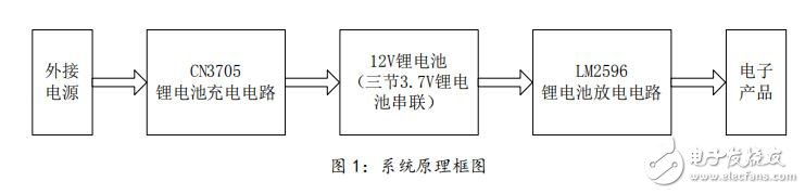
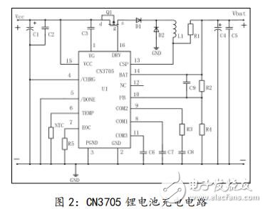
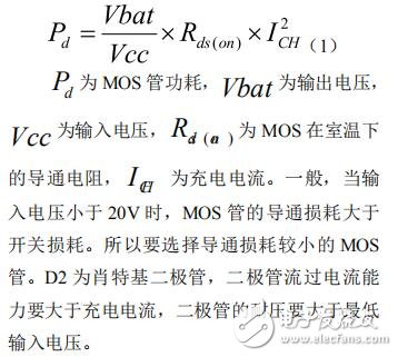
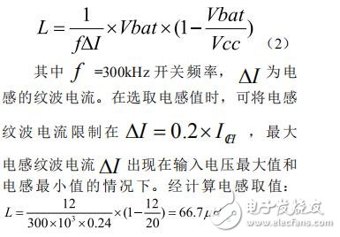
At present, there are more and more consumer electronic products, such as smart phones, tablets, PSP game consoles and other electronic products, which provide great convenience for people's life, work and entertainment. However, these electronic products have a common shortcoming. The capacity of their own lithium batteries is limited, and often because of the lack of electricity, our electronic products cannot be used. In order to solve the problem of battery life, this circuit is designed to integrate lithium battery charging and discharging. As shown in Figure 1. The system is divided into three parts, CN3705 lithium battery charging circuit, 12V lithium battery, LM2596 lithium battery discharge circuit. CN3705 is a buck mode lithium battery charging chip with constant current and constant voltage charging mode. For deep discharge batteries, when the battery voltage is lower than 66.7% of the set constant voltage charging voltage, the CN3705 uses a constant current charging current of 15% to trickle charge the lithium battery. During the constant voltage charging phase, the charging current gradually decreases, and when the charging current decreases to the value set by the external resistor, the charging ends. The chip's input voltage is between 12V and 28V, the maximum operating frequency is 300kHz, and the maximum output current is 5. Figure 2 shows the lithium battery charging circuit composed of CN3705. The circuit structure is buck buck topology. The input voltage is between 14V and 28V, the circuit PWM switching frequency is 300kHz, the maximum output current is 1.2A, and the maximum output voltage is 12.6V. Suitable for charging 3 series 3.7V standard lithium batteries. In Figure 2, the P-channel MOS transistor Q1, Schottky D2, inductor L1, and electrolytic capacitor C1 form a classic buck step-down charging circuit. The choice of Q1 should take into account the conversion efficiency, the power consumption of the MOSFET and the maximum temperature. Factors to be considered include on-resistance Rds(on), total gate charge Qg, input voltage, and maximum charging current. The MOS tube loss power calculation formula is as follows: The transient inductor current changes periodically during normal operation. During the turn-on of the MOS transistor, the input voltage charges the inductor and the inductor current increases. During the turn-off of the MOS transistor, the inductor discharges to the battery and the inductor current decreases. The ripple current of the inductor increases as the inductance value decreases, and increases as the input voltage increases. Have the following empirical formula:
16+ Years Experience Smart Watch manufacturer, ITOPNOO Provide One-stop Smart Wearable devices Solutions For You.
Our Smart Wearable products include android smart watches, Watch For iPhone, Bracelet and Wristband etc.
Leading healthcare navigation services for individuals and families who are generally healthy or face serious medical issues, and health services for employers.
The Trends New Watches Designs. Custom smart watch products designed with the vision of our clients' brands in mind.
Wholesale smart watches,Best Smart Watches,Gifts Wholesalers, smart watch manufacturer TOPNOTCH INTERNATIONAL GROUP LIMITED , https://www.micbluetooth.com