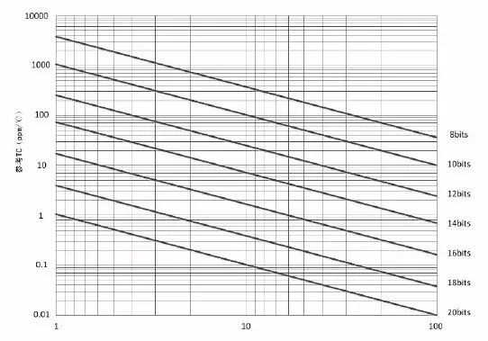
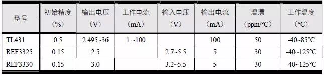
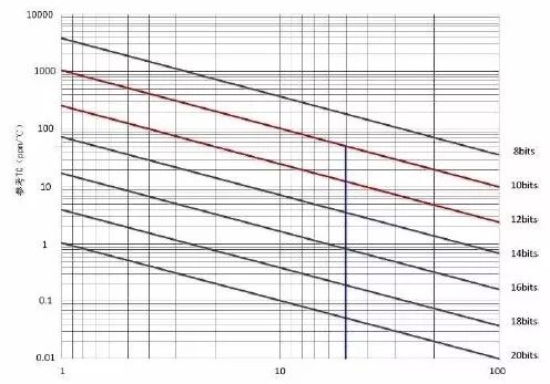
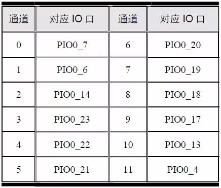
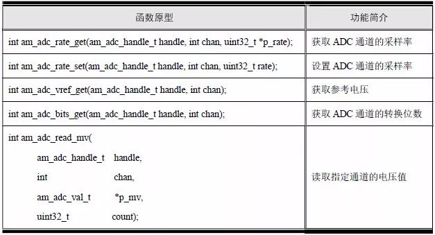
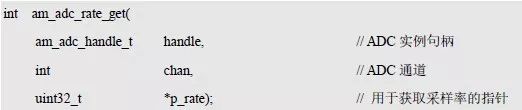
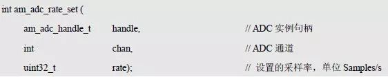
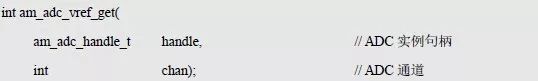
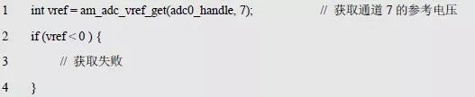
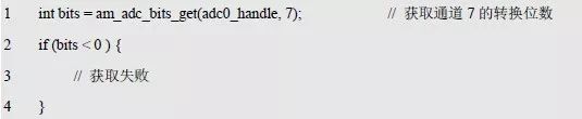
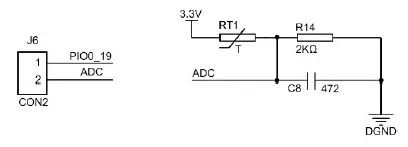
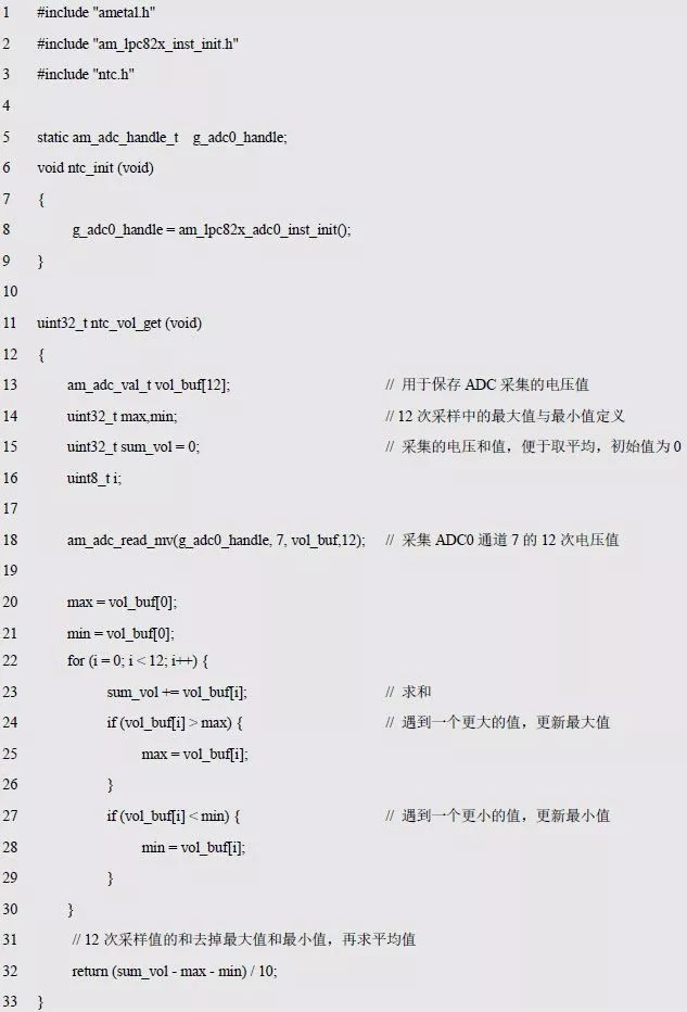
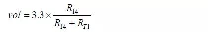
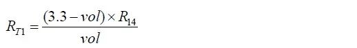
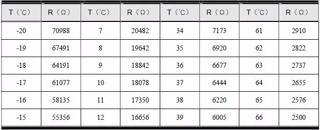
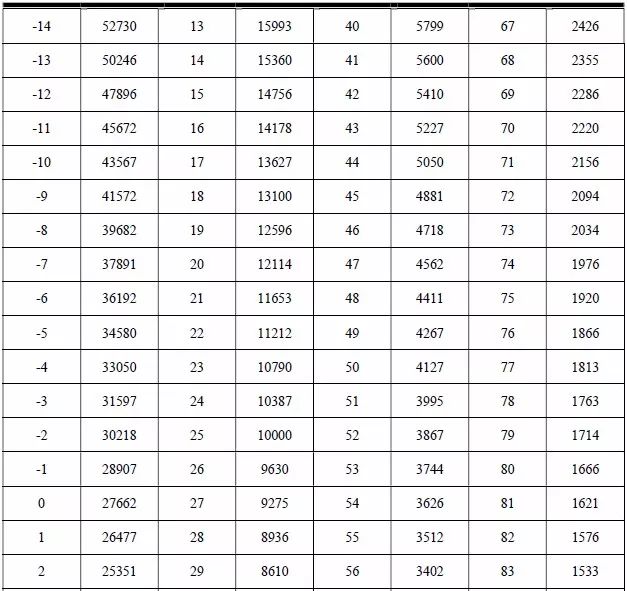
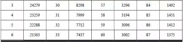
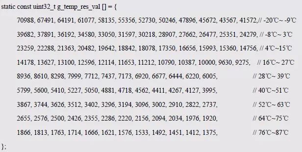
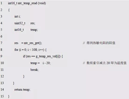
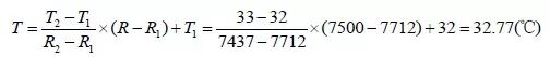
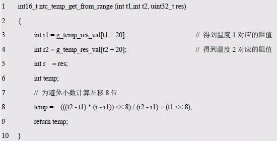
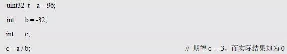
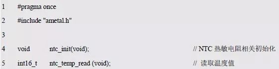
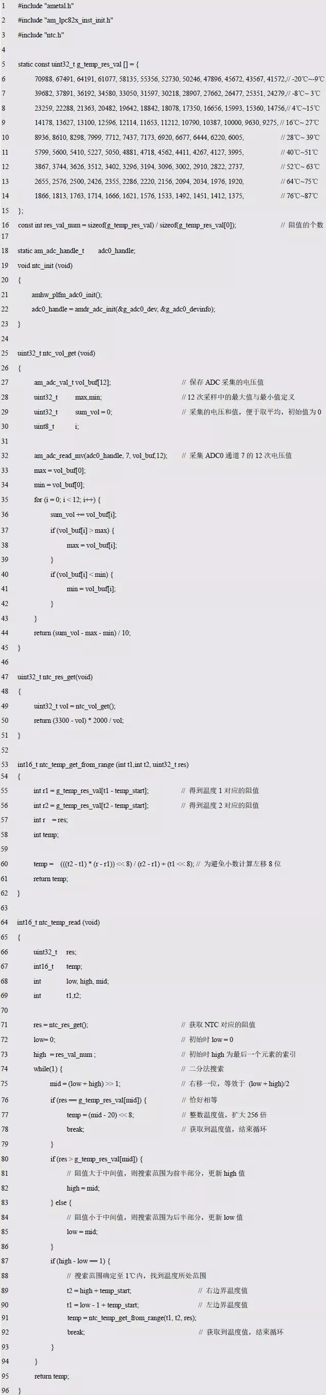
Prof. Zhou Ligong's new book "Programming for AMetal Frameworks and Interfaces (Part 1)" introduces the AMetal framework in detail. By reading this book, you can learn highly multiplexed software design principles and development ideas for interface programming. Focus on your own "core domain", change your own programming thinking, and achieve common progress between the company and the individual. The fifth chapter is to explain AMetal in depth . The content of this article is 5.7 A/D converter. 5.7 A/D converter > > > 5.7.1 Analog to Digital Signal Conversion 1. Fundamental The noise and image signals that we often touch are analog signals. To convert analog signals into digital signals, we must go through several processes of sampling, holding, quantifying and encoding. See Figure 5.4 for details. Figure 5.4 Schematic diagram of analog-to-digital signal conversion An operation of extracting the size of a signal at a certain time interval is referred to as sampling, and its value is a sample value, and the shorter the time interval of extracting the signal size, the more correctly the signal can be reproduced. Since shortening the time interval leads to an increase in the amount of data, the time interval is shortened. Note that the sampling frequency is greater than or equal to 2 times the highest frequency in the analog signal, and the original signal can be recovered without distortion. It takes a certain time to convert the sampled signal into a digital signal. In order to provide a stable value for the subsequent quantized coding circuit, the output of the sampling circuit must be maintained for a while, and the sampling and holding process is completed simultaneously. Although the continuous signal on the time axis is converted into a discontinuous (discrete) signal by sampling, the sampled signal amplitude is still a continuous value (analog). At this time, it is possible to divide at a certain interval in the amplitude direction, determine which interval the sample values ​​belong to, and assign the value recorded in the interval to the sample value. Figure 5.4 divides the interval into 0~0.5, 0.5~1.5, 1.5~2.5, and then uses 0, 1, 2, ... to represent each interval, and rounds the value after the decimal point. For example, 201.6 belongs to 201.5~202.5, then assign 202; 123.4 belongs to 122.5~123.5, then assign 123, such an operation is called quantization. The amplitude of the signal before quantization differs from the amplitude of the quantized signal. This difference will be expressed in the form of noise when the signal is reproduced, so this difference is called quantization noise. In order to reduce this noise, it is sufficient to reduce the interval between steps during quantization. However, reducing the quantization interval causes an increase in the number of steps, resulting in an increase in the amount of data. Therefore, the number of steps to be quantized must also be appropriate and can be determined according to the required signal-to-noise ratio (S/N). Converting the quantized signal into a binary number, that is, a process represented by a combination of codes of 0 and 1 is called encoding, "1" means a pulse, and "0" means no pulse. When the number of quantization steps is 64, the number of bits representing the binary value of these values ​​must be 6 bits; when the number of quantization steps is 256, it must be represented by an 8-bit binary number. 2. The reference voltage The reference voltage is the maximum voltage that the analog-to-digital converter can convert. Taking an 8-bit A/D analog-to-digital converter as an example, this converter can convert an input voltage from 0V to its reference voltage range into a corresponding value representation. The input voltage range corresponds to 4096 values ​​(step size), and the calculation method is: reference voltage / 256 = 5 / 256 = 19.5 mV. It seems that the 10-bit A/D step voltage value is given here, but the above formula also defines the conversion accuracy of the analog-to-digital converter. In any case, the accuracy of all A/D conversions is lower than the accuracy of its reference voltage. The only way to improve output accuracy is to increase the calibration calibration circuit. Many MCUs now have built-in A/D, which means that the power supply voltage can be used as its reference voltage or an external reference voltage can be used. If the power supply voltage is used as the reference voltage, assuming that the voltage is 5V, the measurement result of the 3V input voltage is: (input voltage/reference voltage) × 255 = (3/5) × 255 = 99H. Obviously, if the power supply voltage rises by 1%, the output value is (3/5.05) × 255 = 97H. In fact, the error of the typical power supply voltage is generally 2~3%, and the change of the output voltage on the A/D is very large. 3. Conversion accuracy The output accuracy of the A/D is determined by the combination of the reference input and the output word length. The output accuracy defines the minimum voltage change that the A/D can convert. The conversion accuracy is the A/D minimum step value, which can be obtained by calculating the ratio of the reference voltage to the maximum conversion value. For the 8-bit A/D using the 5V reference voltage given above, the resolution is 19.5mV, that is, the output value of all input voltages lower than 19.5mV is 0, at 19.5mV~39mV The output voltage of the input voltage is 1, and the output voltage of the input voltage between 39mV and 58.6mV is 3, and so on. One way to increase the resolution is to lower the reference voltage. If the reference voltage is reduced from 5V to 2.5V, the resolution rises to 2.5/256=9.7mV, but the highest measured voltage drops to 2.5V. The only way to increase the resolution without lowering the reference voltage is to increase the number of digits in the A/D. For a 12-bit A/D using a 5V reference, the output range is up to 4096 with a resolution of 1.22mV. . In practical applications, there is noise. Obviously, the 12-bit A/D will convert 1.22mV of noise in the system as its input voltage. If the input signal has a noise voltage of 10mV, the noise sample can only be sampled multiple times and the sampled result averaged, otherwise the converter cannot respond to a true input voltage of 10mV. 4. Cumulative accuracy If a 5% error resistor is used at the front of the amplifier, this error will cause the 12-bit A/D to not operate properly. In other words, the A/D measurement accuracy must be less than the sum of its conversion error, reference voltage error, and the sum of all analog amplifier errors. Although the conversion accuracy is limited by the device error, a satisfactory output accuracy can be obtained by separately calibrating each system. If the accurate scaling voltage is used as the standard input and all inputs are corrected with the scaling voltage constant stored in the MCU program, the conversion accuracy can be effectively improved, but in any case it cannot bring about temperature drift or device aging. The effects are corrected. 5. Reference source selection The main factors causing the voltage reference output voltage to deviate from the nominal value are: initial accuracy, temperature coefficient and noise, and long-term drift. Therefore, when selecting a voltage reference, the resolution accuracy, supply voltage, and operating temperature range required by the system are required. When considering the situation, it is not possible to simply select a single parameter. For example, a 12-bit A/D is required to resolve to 1 LSB, which is equivalent to 1/2 12 = 244 ppm . If the operating temperature range is 10 ° C, then an initial accuracy of 0.01% (equivalent to 100ppm), a temperature coefficient of 10ppm / ° C (100ppm offset within the temperature range) can meet the accuracy requirements of the system, because the total caused by the benchmark The error is 200ppm, but if the operating temperature range is extended above 15°C, the benchmark is not applicable. 6. Common reference source (1) Determination of initial accuracy The choice of initial accuracy depends on the accuracy requirements of the system. For a data acquisition system, if an n-bit ADC is used, the full-scale resolution is 1/2 n. If the accuracy of 1 LSB is required, the initial accuracy of the voltage reference is obtained. for: If the influence of other errors is taken into consideration, the actual initial accuracy should be chosen to be higher than the above formula, for example, by the resolution accuracy of 1/2LSB, that is, the result obtained by the above equation is divided by 2, namely: (2) Determination of temperature coefficient The temperature coefficient is another important parameter for selecting the voltage reference. In addition to the accuracy required by the system, the temperature coefficient is directly related to the operating temperature range of the system. For the data acquisition system, assuming that the number of bits of the ADC used is n, and the accuracy of 1 LSB is required, and the operating temperature range is ΔT, then the temperature coefficient TC of the reference can be determined by: Similarly, considering the effects of other errors, the actual TC value is chosen to be smaller than the above formula. The temperature range ΔT is usually calculated on the basis of 25 ° C. The industrial temperature range is -40 ° C to +85 ° C. For example, ΔT can be taken as 60 ° C (85 ° C - 25 ° C) because the manufacturer usually sets the reference temperature at around 25 ° C. The error caused by the change is minimized. As shown in Figure 5.5, it is a very useful quick-checking tool. It is based on 25°C. When the temperature changes from 1°C to 00°C, the 8~20-bit ADC will require the required reference at 1LSB resolution. The TC value is plotted as a graph from which the desired TC value can be quickly found. Figure 5.5 Relationship between system accuracy and reference temperature coefficient TC The TL431 and REF3325/3330 are typical voltage reference products, as shown in Table 5.19. The output voltage of the TL431 can be continuously adjusted from 2.5 to 36V with only two resistors, and the load current is 1~100mA. It is commonly used in adjustable voltage power supplies, switching power supplies, and op amp circuits to replace Zener diodes. The REF3325 outputs 2.5V and the REF3330 outputs 3.0V. Table 5.19 Voltage Reference Source Selection Parameter Table The REF33xx is a low power, low dropout, high precision voltage reference in a small SC70-3 and SOT23-3 package. The small size and low power consumption (5μA maximum current) make the REF33xx family the best choice for many portable and battery-powered applications. Under normal load conditions, the REF33xx family can operate at supply voltages above the specified output voltage of 180mV, with the exception of the REF3312, which has a minimum supply voltage of 1.8V. From the initial accuracy and temperature drift characteristics, the REF3325/3330 is superior to the TL431, but the TL431 has a wide output voltage range and a wide operating current range, even replacing some LDOs. Since the initial accuracy and temperature drift characteristics of the reference are key parameters affecting the overall accuracy of the system, they cannot be used in high-precision acquisition systems and high-resolution applications. For 12-bit AD, which model is selected because the accuracy requires about 0.1% of the acquisition system? The initial accuracy of the measurement system can be eliminated by eliminating the initial accuracy introduced by the system calibration; for the choice of temperature drift, the resolution must be referenced with reference to the 1LSB resolution accuracy, as shown in Figure 5.6. If it is not working in a harsh environment, usually the operating temperature is -10 ° C ~ 50 ° C, the temperature changes at 60 ° C, if considering 0.1% system accuracy, temperature characteristics below 50ppm, then choose REF3325 /3330. Figure 5.6 12bits system baseline selection > > > 5.7.2 Initialization Before using the ADC general purpose interface, the initialization of the ADC must be done to obtain the standard ADC instance handle. The LPC82x contains only one ADC (ADC0). For user convenience, AMetal provides an instance initialization function corresponding to ADC0. The function prototype is: The return value of the function is the ADC instance handle of type am_adc_handle_t, which will be the argument to the handle parameter in the ADC's generic interface. The type am_adc_handle_t(am_adc.h) is defined as follows: Because the ADC instance handle returned by the function is passed as a parameter only to the ADC's generic interface, there is no need to do anything else with the handle, so there is absolutely no need to know anything about the type. It is important to note that if the value of the instance handle returned by the function is NULL, the initialization fails and the instance handle cannot be used. To use ADC0, the ADC0 instance initialization function can be directly called to complete the initialization of ADC0 and obtain the corresponding instance handle: ADC0 supports 12 channels and can collect 12 analog signals for analog-to-digital conversion. Each analog signal is input to ADC0 through the corresponding I/O port of LPC824. The corresponding I/O ports of each channel are shown in Table 5.20. Table 5.20 I/O ports corresponding to each channel > > > 5.7.3 Interface Functions AMetal provides five ADC-related interface functions, as shown in Table 5.21. Table 5.21 ADC Common Interface Functions 1. Get the sampling rate of the ADC channel Get the sample rate of the current ADC channel. Its function prototype is: The unit of sample rate obtained is Samples/s. If AM_OK is returned, the acquisition is successful. If -AM_EINVAL is returned, the acquisition fails due to invalid parameters. The corresponding code is shown in Listing 5.87. Listing 5.87 am_adc_rate_get() sample program Invalid parameters are caused by the fact that the handle is not a standard ADC handle or the channel number is not supported. 2. Set the sampling rate of the ADC channel Set the sampling rate of the ADC channel. The actual sample rate may differ from the set sample rate, which can be obtained by the am_adc_rate_get() function. Note that in an ADC, the sampling rate of all channels tends to be the same, so setting the sampling rate of one of the channels may affect the sampling rate of other channels. Its function prototype is: If AM_OK is returned, the setting is successful; if -AM_EINVAL is returned, the setting fails due to invalid parameters, and the corresponding code is shown in Listing 5.88. Listing 5.88 am_adc_rate_set() sample program 3. Get the reference voltage of the ADC channel Get the reference voltage of the ADC channel. The function prototype is: If the return value is greater than 0, it means that the acquisition is successful, and its value is the reference voltage (unit: mV); if -AM_EINVAL is returned, the acquisition fails due to invalid parameters. The corresponding code is shown in Listing 5.89. Listing 5.89 am_adc_vref_get() sample program 4. Get the number of conversion bits of the ADC channel Get the number of conversion bits of the ADC channel. The function prototype is: If the return value is greater than 0, it means that the acquisition is successful, and its value is the number of conversion digits. If -AM_EINVAL is returned, the acquisition fails due to invalid parameters. The corresponding code is shown in Listing 5.90. Listing 5.90 am_adc_bits_get() sample program 5. Read the voltage value of the specified channel The voltage value of the ADC channel (in mV) is directly read. This function will wait until the voltage value is read. Its function prototype is: Where p_mv is the buffer pointing to the stored voltage value, and the type am_adc_val_t is defined in am_adc.h, ie: Length indicates the length of the buffer and determines the number of actual voltage values. If you want to return AM_OK, it means that the read channel voltage value is successful, and the corresponding buffer has been filled with the read voltage value; if -AM_EINVAL is returned, the acquisition fails due to invalid parameters. The corresponding code is shown in the program list 5.91. . Listing 5.91 am_adc_read_mv() sample program > > > 5.7.4 Temperature Acquisition 1. Voltage acquisition The thermistor is a sensitive component type and can be classified into a positive temperature coefficient thermistor (PTC) and a negative temperature coefficient thermistor (NTC) according to the temperature coefficient. The typical characteristics of thermistors are temperature sensitive, and their resistance values ​​are different at different temperatures. The positive temperature coefficient thermistor (PTC) has a higher resistance value at higher temperatures, and the lower the temperature value, the lower the resistance value of the negative temperature coefficient thermistor. There is a negative temperature coefficient thermistor RT1 on the AM824-Core. The hardware circuit is shown in Figure 5.7. The thermistor RT1 and RK of 2KΩ form a voltage dividing circuit. The MF52E-103F3435FB-A and C8 are used to make the circuit output more stable. When the temperature range is from 0 to 85 °C, the resistance varies from 27.6 to 1.45 KΩ. When the temperature changes, the resistance value of the thermistor changes, and the ADC value collected by the MCU also changes. As long as J6 is shorted through the jumper cap, the voltage of the R14 resistor is directly input to channel 7 of the ADC through PIO0_19, and the voltage value can be collected using the ADC. Figure 5.7 Thermistor Circuit Two functions of ntc.c, as shown in Listing 5.92, one for initialization and one for reading voltage values. Since the final interface is still undefined, only ntc.h was created. Listing 5.92 Acquisition Voltage Value Correlation Function Writing (ntc.c) Ntc_init() is only used to initialize the ADC to get a standard ADC instance handle. Ntc_vol_get() is used to get the voltage value corresponding to ADC channel 7, using the am_adc_read_mv() function. In order to make the results more credible, the median averaging filtering method (anti-pulse interference averaging filtering method) is used for voltage acquisition, that is, the maximum value and the minimum value in the sampled data are removed, and the average value of the remaining data is taken as the final result. In the program, first use the am_adc_read_mv() function to collect 12 voltage values, then sum all the voltage values, find the maximum and minimum values, and finally subtract the maximum and minimum values ​​from the sum value and divide by 10 The voltage is collected and returned. 2. Get resistance Assuming that the acquired voltage value is vol, after dividing by R T1 and R 14 , there are: After a simple conversion, you can get: Using this formula, the acquired voltage value can be converted to the resistance value of RT1. See Listing 5.93 for details. Also add the program directly to ntc.c. Listing 5.93 Obtaining the resistance of the thermistor (ntc.c) In order to avoid fractional calculations, the unit of voltage is unified to millivolts (mV), and the unit of resistance is unified to ohms (Ω). 3. Resistance and temperature After obtaining the thermistor resistance, how will the temperature corresponding to the resistance value be found? Let's start by analyzing the relationship between the thermistor resistance and temperature. The resistance value (RT) and temperature (T) of the negative temperature coefficient thermistor are exponential: Where R T is the NTC thermistor resistance at temperature T (in K, ie Kelvin), R N is the NTC thermistor resistance at the rated temperature T N(K), and B is the NTC thermistor The material constant, also known as the thermal index. Since this relationship is an empirical formula, it has a certain accuracy only within a limited range of the rated temperature T N or the rated resistance value R N . How do I get the value of the material constant B? Obviously, it can only be measured experimentally. It is assumed that in the experimental environment, the zero power resistance value at the temperature T1 (K) is measured as RT1, and the zero power resistance value at the temperature T2 (K) is RT2. Zero-power resistance means that when the thermistor value is measured at a certain temperature, the power consumption applied to the thermistor is extremely low, so that the resistance value of the thermistor caused by its power consumption is negligible. The rated zero-power resistance is the zero-power resistance measured at an ambient temperature of 25 ° C, labeled R25, which is commonly referred to as the NTC thermistor resistance. According to T1, R T1 , T 2 , R T2 and the relationship between temperature and resistance value, we can get: Divide the two equations to get: The logarithm (ln) of e on both sides of the equation is obtained: After transformation, the formula for calculating the B value is: It can be seen that as long as the zero power resistance values ​​corresponding to the two temperature points are measured, the B value can be obtained. Since accurate measurement requires a high-precision temperature measuring instrument and a high-precision resistance measuring instrument, it is difficult to complete under normal conditions. Therefore, manufacturers often provide zero-power resistance values ​​corresponding to temperature points. For example, the thermistor used by the AM824-Core, the manufacturer provides two zero-power resistance values ​​corresponding to the temperature point: R25 = 10000Ω, R85 = 1451Ω. Based on these two temperature values, the B value can be obtained: Note that the temperature in the expression is in Kelvin (K), so you need to convert Celsius (°C) to Kelvin. Its conversion relationship is: When the B value is obtained, the resistance value at a certain temperature can be obtained by using the relationship between the resistance value and the temperature. In the relationship between resistance and temperature, RN is the resistance at the rated temperature TN(K), and the value corresponding to R25 can be used directly, that is, RN=10000Ω, TN=(25+273.15)K. Calculate the corresponding resistance value by taking 60 °C as an example: It can be seen that the above calculation process is very cumbersome, and involves complicated index operations, so the look-up table method is often used. That is, the resistance values ​​corresponding to the respective temperatures are first stored in a table, and the table can be directly looked up when needed. For the AM824-Core thermistor, the manufacturer provides an RT meter as shown in Table 5.22. According to the actual application, only the resistance value corresponding to -20 ° C ~ 87 ° C is listed here, but in fact the thermistor supports the temperature measurement of -40 ° C ~ 125 ° C. Table 5.22 Thermistor RT Table By looking up the table, it can be seen that the resistance value corresponding to 60 ° C is 3002 Ω, and the calculated value is 2981 Ω. Since the previous formula is only an empirical formula, there is often a small difference between the calculated value and the measured value, but overall it is very similar, that is, 2981 Ω is closest to 60 °C. Since the temperature is continuous and spaced at 1 °C, all the resistance values ​​can be stored in a one-dimensional array, that is, the 0 element of the array corresponds to the resistance of -20 °C, and the element of 107 corresponds to the resistance of 87 °C. . To get the resistance corresponding to the temperature, add 20 to the temperature index as an array index. Since the maximum resistance is 70988Ω, each resistor requires a 32-bit data to be saved, and the type of the array element is set to uint32_t. -20 ° C ~ 87 ° C for a total of 108 resistance values, the array size is 108, a total of 108 four-byte memory cells, that is, 108 * 4 = 423 bytes. Note that the resistance values ​​corresponding to only -20°C and -19°C in the table exceed 65535. The resistance values ​​of other temperature values ​​can be represented by 16 bits. Therefore, special treatments can be performed, for example, the resistance values ​​corresponding to -20 ° C and -19 ° C are separately saved. If the temperature range does not include these two temperatures, the resistance values ​​corresponding to the two temperature values ​​can be removed. The ntc.c for saving the temperature corresponding to the resistance is shown in Listing 5.94. Listing 5.94 defines an array that holds the resistance values ​​for each temperature value. Since the starting element of the array is the resistance corresponding to -20 °C, the relationship between the corresponding temperature and the array index is as follows: Corresponding temperature = array index -20 Array index = corresponding temperature +20 Since the difference between the array index and the temperature is 20, if you need to obtain the resistance value corresponding to 25 °C, you should add 20 as the index of the array based on the temperature value. which is: 4. Get the temperature value Although the corresponding relationship between the resistance value of the thermistor and the temperature has been obtained, how to obtain the temperature corresponding to the resistance value? If the resistance corresponds to a temperature that is just an integer, that is, the resistance will be equal to an element in the array, then only one array needs to be scanned. If the resistance is equal, the corresponding temperature can be obtained. See Listing 5.95 for details. Listing 5.95 Obtaining Temperature Values ​​(1) Although the program is simple to implement, it is not practical because the probability that the resulting resistance is exactly the integer temperature is too small. In fact, the resistance obtained is often within a certain range. For example, if the temperature range of 7500Ω is 32°C~33°C, how to determine the temperature value? The difference between 7500Ω and 32°C is 7712Ω, which is 212Ω, and the 7437Ω corresponding to 33°C is 63Ω, which is obviously closer to 33°C. Is it better to take 33°C directly? If the accuracy is not high, the obtained temperature is all integer values. If you want more accurate, for example, the accuracy is required to be two decimal places? Although the exponential relationship is a nonlinear relationship, the corresponding resistance-temperature relationship diagram is a graph, but this curve can be decomposed into several small segments, and the resistance-temperature relationship in each segment is approximated as a linear relationship. For example, the resistance-temperature relationship in the temperature range of 1 ° C is approximated as a linear relationship. Assuming the two endpoints of the interval (R1, T1), (R2, T2), then using the known two-point line equation method, it is easy to get the temperature corresponding to the resistance R (R1 ≤ R ≤ R2): For the above example, if the measured resistance is 7500 Ω, the two endpoints of the interval are (7712, 32) and (7437, 33). Using the above formula, the temperature value can be obtained: Obviously, the temperature thus obtained is more accurate, and the corresponding code is detailed in Listing 5.96. Listing 5.96: Obtaining temperature values ​​based on temperature intervals The signed number is used in the program, and the resistance value is represented by an unsigned number, so the unsigned resistance value must be stored in the signed number before calculation. When an unsigned number is mixed with a signed number, since the unsigned number has a high priority, the signed number is first converted to an unsigned number and then operated, especially in the case where a negative number is involved in the operation. Unexpected results. such as: Why is the result equal to 0? Because a is an unsigned number, when calculating a/b, according to the unsigned number, it will first convert -32 to an unsigned number, that is, 4294967264, 96 is divided by a large number, and the result is naturally 0. At the same time, in order to avoid the calculation of the decimal, the operation result is expanded by 256 times. Since the measured temperature range is -20 ° C ~ 87 ° C, even if it is expanded by 256 times, it will not exceed the range of 16-bit signed number, so a 16-bit signed number is finally returned. Why expand 256 times instead of 100 times? Of course, 100 times better understanding, if you expand 100 times, it means to retain 2 decimal places, the minimum value is 0.01. In fact, the expansion is 256 times the same, and its minimum representation value is 1/256 = 0.00390625, which has higher precision. The LM75B we have used to collect the temperature value, the actual measured temperature value returned by the lm75_read() function that reads the temperature value is also expanded by 256 times. In this way, if the temperature value returned here is also expanded by 256 times, the previous program can be completely reused. In order to get the temperature value using the ntc_temp_get_from_range() function, it is also necessary to find the temperature range in which the resistance corresponds to the temperature. How to get the interval? Since the resistance is sequentially decreasing, the simplest method is to search sequentially. As long as the measured resistance value is greater than the resistance corresponding to a certain temperature in the resistance table, the interval in which it is located can be determined. If you find the interval of resistance 7500 in order, find the resistance 7437 corresponding to the temperature of 33 °C, and find that it is smaller than it, then 33 °C is its right boundary, and the left boundary is the previous temperature value, ie 32 °C, corresponding The code is detailed in Listing 5.97. Listing 5.97 Obtaining Temperature Values ​​(2) In fact, the current search method is too inefficient. If the temperature is 87°C, it is searched 108 times until all the array elements are traversed. Since the resistance is decreasing in order, it is possible to use the dichotomy. That is, each time compared with the number in the middle, the search range can be reduced by half according to the comparison result, and then continue to compare with the intermediate value in the new search range, and the search range can be reduced by half according to the comparison result, and so on. Comparisons can directly narrow the search by half. The following is still taking 7500Ω as an example. There are a total of 108 array elements with an index of 0 ~ 107. The two variables low and high respectively represent the lower and upper bounds of the search range, and mid represents the middle position. (1) Initially, low = 0, high = 107, the middle position is (low+high)/2 = 53 (directly according to C language integer division), 53 position (ie temperature 33 ° C, directly look up table 5.22) The corresponding resistance is 7437, 7437 is less than 7500, so the search range is locked to the upper part, so update high = 53; (2) Continue to search, low = 0, high = 53, mid = 26, 26 position corresponding resistance is 21363, 21363 is greater than 7500, so the search range must be in the second half, update low = 26; (3) low = 26, high = 53, mid = 39,39 The corresponding resistance is 12596, 12596 is greater than 7500, so the search range is still in the second half, update low = 39; (4) low = 39, high = 53, mid = 46, 46 The corresponding resistance is 9630, 9630 is greater than 7500, so the search range is still in the second half, update low = 46; (5) low = 46, high = 53, mid = 49,49 The position corresponding to the resistance is 8610, 8610 is greater than 7500, so the search range is still in the second half, update low = 49; (6) low = 49, high = 53, mid = 51, 51 The corresponding resistance is 7999, 7999 is greater than 7500, so the search range is still in the second half, update low = 51; (7) low = 51, high = 53, mid = 52, 52 The position corresponds to a resistance of 7712, and 7712 is greater than 7500, so the search range is still in the second half, updating low = 52. At this point, since there is only one difference between low and high, it can no longer be divided into two parts. Therefore, it is determined that the value to be found must be between positions 52 and 53, that is, the temperature range corresponding to the resistance is 32 ° C ~ 33 ° C, The search ends here. For 108 elements, search by dichotomy, search up to 7 times, and the corresponding code is shown in Listing 5.98. Listing 5.98 Obtaining Temperature Values ​​(3) At this point, you can directly call ntc_temp_read() to get the temperature value. After the related functions have been written, the ntc_init() and ntc_temp_read() functions are declared in Listing 5.99 (ntc.h). For details, see Listing 5.100 (ntc.c). Listing 5.99 ntc.h file contents Listing 5.100 ntc.c file contents Ntc.c has two new variables compared to the previous code: (1) The new variable res_val_num is used to represent the number of array elements. In the range search, the previous fixed value 107 is modified to the number of array elements, so that the array elements can continue to increase backwards, for example, increase to -20 ° C ~ 125 ° C, then all code does not need any modification. (2) The new variable temp_start is used to indicate the starting temperature value of the resistance table. The previous code has a fixed starting temperature of -20 ° C. If the forward extended temperature range is -40 ° C to 125 ° C, the program must be modified accordingly. When the variable is added, when the temperature range is extended forward, only the value of the variable needs to be modified. At this time, the starting element of the array is the resistance corresponding to the temp_start temperature, so the corresponding temperature has the following relationship with the array index: Corresponding temperature = array index + temp_start, array index = corresponding temperature - temp_start The sample program can directly modify the previously written “Intelligent Temperature Controller†program, and use the thermistor to obtain the temperature value to replace the previous LM75 to obtain the temperature value. Just modify the 3 lines of code: "#include "lm75.h" is modified to #include"ntc.h", lm75_init() in the am_main() function is changed to ntc_init(), lm75_read in the am_main() function ( ) modified to ntc_temp_read()", and other complicated keyboard processing and digital tube display can be reused. Quick Description : Vome Box Mini Tpd Version,Vome Box Mini Tpd Version Vape ,600 Puffs Vape ,Dazzle Light Glowing E-Cigarette Shenzhen Kester Technology Co., Ltd , https://www.kesterpuff.com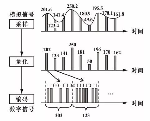


☑ Salt Nicotine:5%/3%/2%/0%
☑ Puffs:600 puffs
☑ Capacity:2ml
☑ 400 pcs per carton
☑12 flavors available
☑ 400mah
☑ Cotton Coil
Flavor List:
1.Blue Raspberry Ice
2. Energy Drink
3.Watermelon Ice
4. Strawberry Kiwi Ice
5. Grape Ice
6. Sour Apple
7. Blueberry Cheesecake
8.Vanilla Custard
9. Pink Lemonade
10. Mixed Berry Ice
11.Strawberry Watermelon
12.Banana Milk
