Design of software ring pulse distributor based on DMA controller
Abstract: This paper introduces the design of a stepping motor software ring pulse distributor based on DMA controller. The design has the advantages of easy implementation, low CPU resources, and high speed.
1 IntroductionStepper motors are important actuators in digital control systems and are used in a wide variety of control systems. The function of the stepping motor is to convert the pulse electric signal into mechanical angular displacement. When the motor winding inputs an electric pulse, the motor rotor rotates by a step angle. The angular displacement and angular velocity of the motor rotation are respectively input by the electric pulse and the electric pulse. The frequency is determined, and the control accuracy is generally determined by the step angle. Since the working principle of the stepping motor is that the windings must be energized and changed in a certain order to work normally (A AB B BC C CA A AB B ...), the part that completes the change rule of the energization sequence is called a ring pulse distributor. The ring distributor design of the stepper motor can usually be implemented in both hardware and software. The software distributor is characterized by the ability to make full use of computer resources to reduce hardware costs, and to apply multi-phase pulse distribution, but it will take up computer running time and may affect the running speed of the stepping motor. In this paper, by using the DMA controller, a pulse distributor with fast response and low CPU time is designed.
2 Pulse distributor design based on DMA controller 2.1 Stepper motor drive principle controlled by microcomputerThe block diagram of the stepper motor drive circuit controlled by microcomputer is shown in Figure 1. The system consists of a single chip microcomputer, a ring pulse distributor, and a power amplifier. The control process of the stepping motor is generally completed by a single chip microcomputer and a ring pulse distributor, and the power amplifier drives and controls the motor operation according to the control law. The pulse signal output from the computer or the ring distributor has a small current and power, and cannot directly drive the stepping motor to rotate. The pulse signal must be amplified by power to drive the stepping motor to rotate. The stepping motor is controlled by a microcomputer, the control circuit is simple, the control scheme is changed easily, and the adaptability is strong.
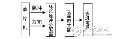
Figure 1 block motor drive principle block diagram
The software distribution method of the ring pulse distributor is completely realized by software programming to realize the phase sequence signal distribution of the stepping motor, and the method of outputting the control signal directly from the output signal port of the microcomputer to realize the pulse distribution. The software frequency division is to use the look-up table or calculation software to control the pulse frequency division, read the data in a certain order (forward reading or reverse reading data to control the motor to reverse), and output the corresponding electrical signal through the output interface. Power amplification is provided to the corresponding motor windings to control motor operation. The speed of the motor is determined by the frequency of the input pulse signal. That is, the motor speed control is achieved by controlling the frequency of the input pulse signal. The steering of the motor can be achieved by controlling the sequence in which the excitation signals are loaded.
The software pulse divider generates control waveforms for the motor windings based on pulse frequency and steering control requirements. Taking the two-phase stepping motor as an example, the excitation state transitions of forward and reverse are shown in Table 1. The above conversion table can be stored in the memory table, the data is cyclically read at a certain frequency, and the corresponding pulse signal is output.
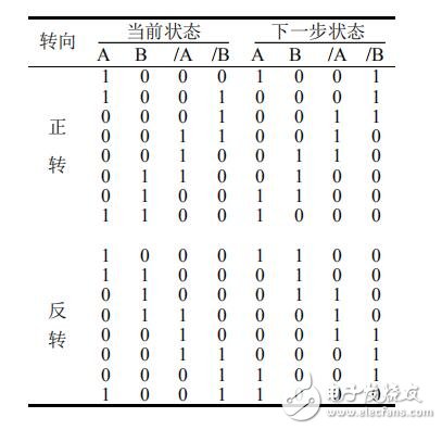
Table 1 Stepping motor winding energization state conversion table
2.2 Basic Principles of DMA ControllerDMA, direct memory access, is a fast data transfer mechanism. The importance of DMA technology is that it does not require CPU intervention when accessing data, which increases the efficiency of the system's execution of applications. Another benefit of using DMA to transfer data is that data is transferred directly between the source and destination addresses, without the need for intermediate media. The DMA has a higher priority for bus control than the CPU, so data can be sent from the source address to the destination address in a very short time after the DMA request occurs.
In order to ensure the control accuracy of the stepper motor, the four bits of data in the memory table must be simultaneously sent to the output port at equal time intervals. The implementation of pure software is more difficult to guarantee the accuracy of time control because of the uncertainty of software execution. Some documents are implemented in a more common way than external EPROM [2]. However, the method of external EPROM must add a device, which increases the complexity of the circuit design and increases the cost.
The DMA controller is an on-chip resource that is common to all microcontrollers. Taking the timer interrupt as the DMA request factor, the DMA controller directly transfers the memory table data to the port output, which achieves the same control precision as the external EPROM, and does not increase the extra time and resources brought by the CPU for data transmission. Consumption.
2.3 DMA controller based pulse distributor system design 2.3.1 system working principleTake Renesas' MCU M16C/62P[2] as an example, the principle is shown in Figure 2. First, the forward and reverse state transition tables of Table 1 are respectively stored in the memory table. Then, start to initialize the DMA controller: set the DMA request factor to the timer B4 interrupt, the DMA data source is the starting address of the above memory table, and the transmission purpose is to connect the 4-bit general-purpose I/O port of the external power amplifying circuit; The length of the table sets the DMA counter so that it loops out of this memory area. Finally, initialize TmerB4: set TImerB4 to work in timer mode, take 3MHz clock as an input reference clock, calculate and set the timer count value according to the speed requirement. After the initialization is completed, the control signal of the stepping motor can be generated by controlling the timer B4. When the motor is controlled to rotate, the timer B4 is turned on to start counting, and an interrupt is generated when the count value is reached. Whenever an interrupt occurs in timer B4, a DMA request is generated; at this time, the DMA controller reads 4-bit data from the memory table and transmits it to the output port, which corresponds to the stepper motor; at the same time, points to the memory table. The pointer also goes further, pointing to the next state vector to be output. The count value of the timer also needs to be reloaded at the time of the interrupt to generate the next interrupt. When the timer generates an interrupt at a certain frequency, the pulse output is continuously generated, and the motor runs at a certain speed. To control the motor to stop, stop counting the timer, that is, stop the pulse output, and the motor stops rotating.
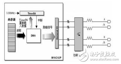
Figure 2 Schematic diagram of DMA-based software ring pulse distributor
KW4-Dustproof Miniature Micro Switch
Features
â—† Inner Housing tunnel design, silicone ring sealing design, stable
sealing IP60.
â—† Small Compact Size,Safety Approvals.
â—† Long life & high reliability.
â—† Wide Range of wires Terminals.
â—† Variety of Levers.
â—† Suit of harsh environment applications, Such as vacuum cle
Wireless Micro Switch,Micro Touch Switch,Ip60 Dustproof Switch,Dustproof Miniature Micro Switch
Ningbo Jialin Electronics Co.,Ltd , https://www.donghai-switch.com