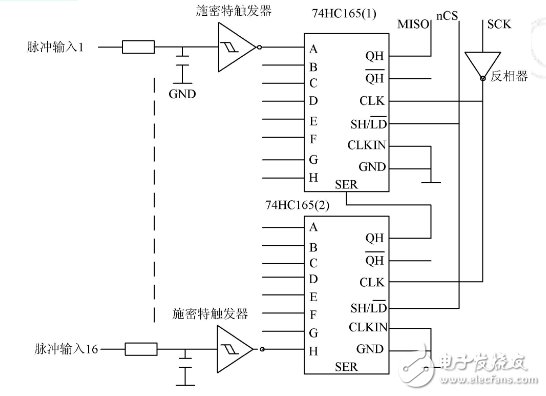
The remote meter reading system not only saves human resources, but more importantly, it can improve the accuracy of meter reading and reduce the bill errors caused by estimation or transcription. Therefore, this technology is more and more popular among users. The remote meter reading system generally includes three parts: a host computer, a concentrator, and a collection terminal. The collection terminal is an intermediate device between the concentrator and the electric energy meter, and mainly has the functions of power data collection, processing, storage and forwarding; according to different energy meters, the power collection terminal adopts intelligent communication mode (protocol) or pulse acquisition. The method collects data and stores the collected data periodically and selectively with a certain algorithm or program, and transmits the real-time or historical electricity data to the concentrator in the format and content required by the concentrator. Because the remote meter reading system based on RS485 bus is not only low cost, but also has the advantages of stable data transmission, high reliability, long transmission distance, fast speed and strong anti-interference ability, this paper introduces a remote copying based on RS485 bus. The design of the table system acquisition terminal, the collection terminal can not only collect the power data of the pulse type electric energy meter, but also can collect the electric quantity data of the electric energy meter with the RS485 interface. The hardware structure of the collection terminal is shown in Figure 1. Figure 1 is a hardware block diagram of the acquisition terminal The microprocessor of the acquisition terminal uses Philips' ARM7 core-based controller LPC2131. It has 8kB of on-chip static RAM and 32kB of on-chip FLASH program memory. It has two 32-bit timers and two 16C550s. The industry standard UART and two high-speed I2C buses, in addition, he also integrated the watchdog and real-time clock on-chip. The acquisition terminal expands two RS485 interfaces with two UARTs, wherein RS485 interface 1 communicates with the concentrator, and RS485 interface 2 communicates with the energy meter with RS485 interface. The memory adopts serial E2PROMAT24C256. The serial E2PROM has the characteristics of small size, low power consumption and simple hardware interface. It can be directly connected to the I2C bus of LPC2131. The acquisition terminal expands I/O through the SPI interface, in which 16 I/O inputs are expanded for 16-channel pulse input, and 16 I/O outputs are extended for digital display circuits. The address of the acquisition terminal is set by 8 address switches, and a mode selection switch is used to select whether the acquisition terminal operates in the pulsed energy meter mode or the RS485 energy meter mode. The pulse acquisition circuit of the acquisition terminal is realized by expanding the I/O input with the SPI interface. Its hardware circuit diagram is shown as in Fig. 2. Figure 2 pulse acquisition circuit The SPI interface performs I/O expansion through two 74HC165s. The 74HC165 is an 8-bit in-serial shift register in which CLK and CLKIN are clock inputs; QH and QH are a pair of serial data outputs with opposite logic levels; SER is a cascade input; SH /LD is the preset control terminal. When it is low level, the data of the parallel data terminal is placed in the internal register of the 74HC165. When it is high level, the serial shift operation is performed. The two 74HC165s are connected by cascading, and their CLK is connected to the SCK of the SPI interface. Since the SPI interface also extends the digital display circuit through two 74HC595s, in order to enable the SPI timing to satisfy both chips simultaneously. Timing requirements, so the SCK of the SPI is directly connected to the SCK of the 74HC595, and the inverter is connected to the CLK of the 74HC165, and the data input and shift operations are controlled by an I/O line nCS. When nCS outputs a low level, 16 pulses enter the 74HC165 internal register, and when nCS outputs a high level, 16 pulses are input through the serial input MISO. In order to eliminate jitter during pulse input, a capacitor and a Schmitt trigger are added to the input to perform debounce processing. Best Rechargeable Vacuum Cleaner,Rechargeable Hand Vacuum Cleaner,Small Rechargeable Vacuum Cleaner,Cordless Rechargeable Vacuum Cleaner Ningbo ATAP Electric Appliance Co.,Ltd , https://www.atap-airfryer.com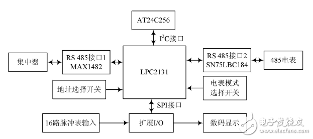
Design and Implementation of Remote Meter Reading System Acquisition Terminal Based on RS485 Bus
1 Introduction