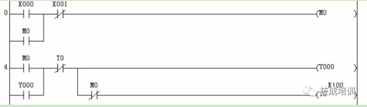
1. I want to use the normally open contact of the timer in 20 places in the program? If the timer expires, do these 20 normally open contacts act together? A: Yes, because the timer contact (normally open or normally closed) is a programming device. It can be used infinitely in the program. Equivalent to having wireless contacts for you to use. These 20 contacts do not work together. The program running of the PLC is performed line by line by progressive scan. When scanning to that line, the contact of that line will be activated. Therefore, strictly speaking, these 20 contacts are limited in action, not in action. 2, the book said that the timer only has a power-on delay contact, I want to use the power-off delay contact how to do? Answer: The timer only has the power-on delay contact. If you want to use the power-off delay contact, you can only do it by programming the power-off delay program. The following figure shows the program for a power-off delay disconnection for reference. 3. I saw the T5 D100 in someone else's program. I don't understand the timing value of this T5. A: The timer time setting value of timer T5 D100 is the value of data register D100. This is the indirect setting method of the timer timing. The advantage of indirect setting is that changing the value of D100 is equivalent to changing the timer timing setting. 4. What is the current value of the timer? What is the current value? A: When the timer is driven to start timing, its value changes from 0 to the set value. This constant value is called the current value of the timer. The current value provides the user with a function of using the timer, that is, in conjunction with the contact comparison command, the output can be controlled at any point within the set value range. 5. How to improve the timing accuracy of the timer? A: The timer is divided into three types according to the count clock: 100ms, 10ms and 1ms. The difference is that the program of the timing time is different. The 100ms timer is changed according to the 0.1s program, and the 1ms timer is changed according to the 0.001s program. If you want to improve the accuracy of the timer, use the 1ms timer. 6. What are the three elements of the timer? A: The three elements of the timer are the start of the timer, the contact action and the reset. 7, I have not understood why in the subroutine, to use the T192-T199 timer? Isn't it possible to use other timers? A: In the subroutine, you can use either the normal timer or the subroutine-specific timer T192-T199. The difference between the two is that the normal timer is only counted when the subroutine is executed. If the subroutine is not executed, the timing is interrupted. In this way, the accuracy of the timing is affected, and timing errors occur. The T192-T199 will not. A dedicated timer is started in the subroutine even if the subroutine is not executed. The timer continues to time, which ensures the accuracy of the timing. 8. What is an integrated timer? What is the difference between him and the general-purpose timer? A: The integrated timer is also called the power-off hold timer. The difference between this and the general-purpose timer is that the integrated timer can keep the timing when the timing is stopped due to the disconnection or power-off caused by the integrated timer. The current value. After the driving condition is turned on or after power-on, the timing will continue on the basis of the original timing until the timing reaches the set value. 9, teacher, please tell us in detail how to make the timer reset knowledge? A: The timer reset is different depending on the reset mode. For general-purpose timers, the start and reset are determined by the drive conditions. When the drive condition changes from a guide to a reset, the timer is immediately reset. In addition, when the PLC is powered off, the timer is also automatically reset. For the integrated timer, it is not reset due to the open or power-off of the drive condition and must be reset using the RST instruction. Of course, the normal timer can also be reset with the RST instruction. 10. Does the timer T5 K10 have its timing setting of 10S? A: The timer set value is the set value multiplied by the clock period of the timer's clock pulse. Differently addressed timers have different clock cycles. All timers are divided into three clock cycles of 100ms, 10ms and 1ms. The same set value, but because the addressing is different due to the set time value, for example: T5 k10 timing time is 1s T243 K10 timing time is 0.1s T275 K10 timing time is 0.01s Timer addressing and clock cycle relationship can be found in the data or manual 11. In the ladder program, how is the current value of the timer represented? A: In the program, the current value of the timer is just as the operand of the function instruction. It is represented as the addressing of the timer. E.g: RST 248 resets the current value of timer T248 MOV T10 D0 transfers the current value of timer T10 to D0 12. Reset the timer. What changes have occurred in the timer? A: The timer resets mainly to generate the following actions. 1. The current value of the timer becomes 0. 2. The contact of the timer is restored to the initial state (ie, normally open to normally open, normally closed to normally closed) 13. Ask the predecessors. When the timer reaches the set value, if the driving condition is still established, will the timer continue to count? Answer: When the timer reaches the set value, if the driving condition is still established, the current value of the timer will not change, and the set value will remain unchanged. Will not continue to time. Wait for the timer to reset. 14. Why does the timer T0 K40000 have an error that the input does not go into the input? A: The timer set value register is a 16-bit data register with a maximum value of K32767. K40000 has exceeded this maximum, so you cannot enter a ladder. 15. Teacher, what is the set time of the T0 K-500? A: The timer value cannot be set to a negative value. If it is set to a negative value, its timing time is set to 0 seconds. 16. Teacher, I don't know the timing time setting value of T10 K100V0 in the program? Can you tell me something? A: T0 K100V0 is the index setting of the timer. The timing value is related to the value of V0. The timing value is K100+(V0). For example, (v0)=k10, the timing value is K100+(V0), and the timing time value is 11 seconds. 17. Teacher, I see two digital switches on the big one. The worker told me that this is used to modify the time setting. I want to understand how it changed the time setting. A: The timer setting can be changed externally using the digital switch. The setting steps are: 1. Use the B1N instruction to convert the 8421BCD code of the external digital switch into a hexadecimal number and store a data register, such as D10. 2. Set D10 to the set value of the timer, for example, T0 D10. 3. In this way, changing the value of the digital switch is equivalent to changing the set value of the timer in the PLC. 18. Teacher, I don't want to use the touch screen to change the setting value of the timer. Because it is too expensive, can you introduce me to other methods to change the setting value of the timer from the outside. A: In addition to using the text display and touch screen to change the set value of the timer, the early PLC's timer set value is to change the set value by externally connecting various switches. These methods are simple, practical and costly. Low, the disadvantage is that it takes up various inputs and switches to change the set value. These methods are simple, practical and low in cost. The disadvantage is that they occupy more input ports. 1. External button input: design program. Use the button to increase or decrease the timing time (0.1 seconds or 1 second) every time you press 1 so that you can estimate the timing time by the number of two button actions. 2. External switch input: Design program, input the preset time of pre-lighting setting with different configuration of switch. 3. An external set of dial switches; the dial switch can form a set of binary numbers (N is the number of switches), and the PLC sends the N-bit binary number into the memory by the instruction as the set value of the timer. This is the early human-machine dialogue mode of PLC. Comparing the above three methods, the DIP switch program is simple in design and accurate in setting value. 4. External digital switch; the program uses the function command BIN to directly send the decimal value of the digital switch to the PLC's memory as the set value of the timer. This is a method that is still in use today. 5. External button input: Press 10 buttons (often reset) at the input end. Through the function command TKY, the external key input sequence is sent to the PLC memory as the set value of the timer. The explanation of several methods of appeal, external wiring and programming are detailed in Chapter 4 of the book "Introduction to Mitsubishi FX3U PLC Application and Programming" by Li Jincheng. 19. My control object is controlled by the hour delay. If it is completed by multiple timer relays, it is too complicated. Is there any other way? A: Multiple timers can reasonably extend the timing, but more timers are used. Also make accurate calculations. If it is only accurate to the hour, you can use the timer command HOUR. Its basic function is to accumulate the closing time of the driving condition when the driving condition is established. When the time reaches the set time, it drives the preset command, HOUR. The set time of the command is always in hours. 20. The teacher of the training class said that the counter must be cleared before use. Why? A: Yes. Before using a counter in the program, it must be cleared first, because the counter's residual count value will not be automatically cleared after the last use. It must be cleared by the RST instruction, otherwise it will affect the subsequent count. 21, I use the command MOV C210 D0 to transfer the current value of C210 to D0, the transmission result is wrong, why? A: The C210 is a 32-bit up/down counter. It is only applicable to the DMOVC210 D0. An error will definitely occur with the 16-bit instruction MOV. 22. When I use X0 to drive the counter C0 K100, why is the counter not reset when X0 is disconnected? A: This is the problem that students use to understand the counters. The driving condition of the timer is also the condition for the timer to be reset. The timer is reset as soon as the driving condition is disconnected, whether the timer is running or counting. The driving condition of the timer is the counting object of the counter. That is, the driving condition is turned on and off once, and the counter is counted once. The reset of the timer must be performed with the RST instruction. 23, teacher, I use a counter C10 to count an open-ended code wheel, but when the code wheel turns fast, it is found that the count is very inaccurate, why? Answer: PLC adopts the cyclic scan mode of operation, and collects the status of the external port of the PLC in one scan cycle. Therefore, during the execution of the user program. If the state of the external port changes, the PLC will ignore it. If the counter is used to change the external input, it cannot be accepted by the timer. This produces a counting error. You can mention that the code wheel is faster. The pulse input time has been shorter than the PLC scan time and many pulses are no longer countable by the counter. A phenomenon of inaccurate counting has occurred. 24. Does the PLC counter have requirements on the speed and number of input pulses? A: The counter of Mitsubishi FX PLC is required for the frequency of the pulse input. For the internal signal counter, the period of the pulse signal is required to be greater than 2 times the PLC scan period. For example, a PLC with a scan period of 50ms should have a pulse input frequency of no more than 10HZ. For the high-speed counter, it works in the interrupt mode, and has nothing to do with the scan period of the PLC. Therefore, its input pulse frequency is affected by hardware and software filtering, generally up to several tens of KHZ. 25, teacher, what is the ring counter? A: The so-called ring counter means that the counter is counted without end, and can be continuously counted down. However, this count is cyclically counted along a certain counting mode, that is, it is called a ring counter. The current value of the count is continuously increased. When it is increased to 32767 (16-bit counter), if a pulse is added, the current value is not 32768 and becomes -32768. Continue counting, it will change from -32768 to 0, continue to be 0 becomes 32767. This cycle is never ending. The subtraction count is reversed. The count of the ring counter is shown below. 26. One of my alumni said that the set value of the counter can be set to a negative number, is it? What does it mean to be set to a negative number? Answer: When the counter is a 32-bit up/down counter, its set value can be set to a negative number. When the counter is added or subtracted, a ring counter will change its current value after reaching the preset set value. The way it is done. Can count to a negative value. Therefore, the up-down counter can be set to a negative value. Setting a negative value is just a count comparison set point. There is no special meaning. 27. During the counting process, the counter suddenly changes the current value of the counter. How will the counter continue to work? A: The counter suddenly changes the current value during the counting process, which will have a certain impact on the counting process. For the increment counter, if the changed current value continues to count down. If the current value after the change is greater than the set value, the current value immediately becomes the set value, and the contact also acts immediately. For the 32-bit up-down counter, the counter will continue to count at the current value after the change, the contact will not operate, and the contact action time will still be executed according to the original regulations. 28. Should the counter be reset with the RST instruction? A: All counters must be reset with the RST instruction. In addition, the incremental counter is automatically reset after a power failure. 29. When the preset setting value of the counter is the input action pulse and the set value is reached, the contact will act? A: For the incremental counter, it is generally understood that the count starts from 0, and the contact action after reaching the set value can achieve the purpose of counting. But for the 32-bit up and down counter. The set value is actually a comparison value, and the direction can be arbitrarily changed in the middle of the count to form an up-down counter. When the current value reaches the comparison set value, the contact performs the action as specified. 30. For the incremental counter, his set value is related to the action of the contact. I feel very clear, but for the 32-bit up and down counter, I always can't understand the law of the contact action. Teacher, can you give me Tell me about it? A: Indeed, the 32-bit up-down counter contact action manual is not very clear, and its action law is also more complicated. The contact action of the up-down counter is divided into different counts and countdowns, and the contact action For the normally open contact (the opposite of the normally closed contact), when the up count reaches the set value, the contact operates and turns from OFF to ON. If it is ON, it remains ON. When the countdown reaches the set value, the contact turns from ON to OFF, and if it is OFF, it remains OFF. Whether it is counting up or down counting. If the counter RST signal is given, the current value of the counter is immediately reset to 0, and the period contact is also restored to its original state. 31. When the counter reaches the set value, if there is still a pulse signal input, will its current value change? A: When the counter reaches the set value, if there is still a pulse input, the incremental counter keeps the current set value unchanged, and the 32-bit up-down counter still counts. 32. What are the requirements for the counter pulse waveform? Can you count both pulse waveforms? Answer: The counter does not have any requirement for the counting pulse waveform. It has nothing to do with whether the pulse waveform is a periodic pulse or not. It only counts the ON/OFF of the input drive conditions. Newmax Electronics Co.,Limited , https://www.advvape.com