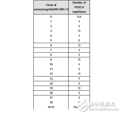
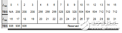
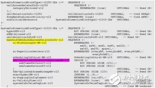
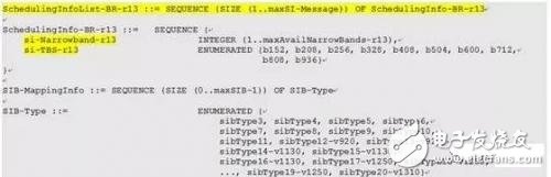
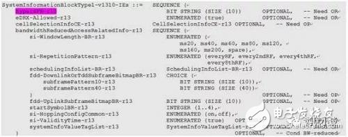
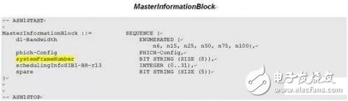
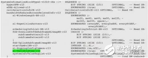
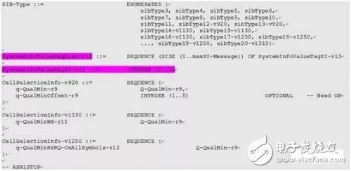
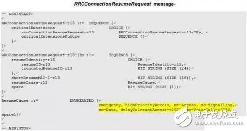
When we talk about NB-IoT, we always mention the concept of eMTC. What exactly is eMTC? Do you really understand it? eMTC (enhanced Machine-TypeCommunicaTIon) terminals mainly refer to those cheap and low complexity object terminals, which have lower cost/benefit, lower rate and are not sensitive to delay, so such terminals Tx/ The ability to receive and receive Rx antennas is also greatly simplified. The Cat.0 (Category 0) terminal needs to decode the SIB1 to confirm whether the network side allows the Cat.0 terminal to access. If the SIB1 indicates that the Cat.0 terminal is not supported, the network side prohibits the access, and the terminal considers that the cell is prohibited from camping ( Cell barred). The network side may determine whether the UE is a Cat. 0 terminal by using a LCID (LogicalChannelID) of the CCCH request initiated by the UE and a capability of the UE. The S1 signaling also includes the UE radio capability into the paging message, and the eNB provides the capability information of the UE to the MME, and the MME provides the terminal capability information to the eNB through the paging request. The eMTC terminal is mainly divided into two types. One is a Bandwidth Reduced Low complexity UE (BL UE) narrowband low complexity UE, which is referred to as a BL UE. Such a terminal can work on any LTE system bandwidth, and only 6 in the uplink and downlink frequency domain. PRB (corresponding to an LTE system with a channel bandwidth of 1.4 MHz). When the cell MIB includes SIB1 scheduling information supporting BLUE, the BL UE may camp to access the cell, otherwise the cell is considered to be prohibited from accessing. Another type is called UE in EnhancedCoverage, which is a UE that supports coverage enhancement. Such terminals support the use of coverage enhancement to access the cell. Protocols (R13) require two coverage enhancement modes, Mode A and Mode B. For BL UEs, coverage enhancement mode A is at least mandatory. The terminals supporting the coverage enhancement class are not necessarily narrowband low complexity terminals (BL UEs). Such terminals support measurement reporting and network side control switching, and like the BL CE, it is not necessary to detect SIB message changes in the connected state. The two types of eMTC terminals are defined from two dimensions of performance. The BL UE is defined from the system bandwidth and the degree of technology. The coverage enhanced terminal is defined from the coverage enhancement function. The classification of these two types of terminals is not latitude and longitude, which means that BL UEs can have coverage enhancement functions, and the terminal categories with coverage enhancement functions can even be extended to LTE user terminals. In summary, the BL UE is a simplified version of the coverage enhanced class terminal. To some extent, the understanding of eMTC technology can be considered as a simplified LTE version, so the design of many mechanism processes is the same. The MIB transmission period is the same as LTE, which is 40 ms, that is, the MIB starts to transmit the 0th subframe of the radio frame of SFN mod4=0, and repeats the transmission on the 0th subframe of the other radio frame. In order to ensure that the MIB can be correctly demodulated, for an FDD or TDD system supporting eMTC and having a system bandwidth greater than 1.4 MHz, the MIB can additionally transmit repeatedly in other subframes, for example, the FDD system transmits a wireless before each MIB radio frame. The subframe 9 of the frame is transmitted, and the TDD system additionally repeats transmission in the subframe 5 of each radio frame of the current transmission MIB. The MIB fixedly occupies 6 physical resource blocks in the frequency domain (for example, the 0th slot of the 0th subframe occupies 0-4 OFDM symbols, and the 0th subframe No. 1 slot occupies 4-6 OFDM symbols). SIB1 also adopts a fixed scheduling mode with a period of 80ms. In addition to repeating transmission in subframe 5 of every two radio frames like LTE, additional repeated transmissions are added in a fixed scheduling period of 80ms. The system message of the extra repeated transmission is named SystemInformaTIonBlockType1-BR, and the TBS format of the extra repeated transmission and the number of repetitions are clarified by the schedulingInfoSIB1-BR field in the MIB, and the UE can determine the TBS (transport block size) by using the SIB1-BR scheduling information in the MIB. And the number of repetitions within 80 ms, and the time domain (radio frame, subframe) and frequency domain position of the repeated transmission can be determined according to the number of repetitions, the system format (FDD/TDD), the cell physical identification ID, and the allocated bandwidth, respectively. For some eMTC terminals that do not have the demodulation broadband ("6PRB" SIB1 capability, it is especially important to demodulate additional SIB1-BR retransmission information. Figure 1 Scheduling information about SIB1-BR in the MIB Table 1 Mapping between the Scheduling InfoSIB1-BR field and the number of SIB1-BR retransmissions (0 means that SIB1-BR is not scheduled) Table 2 Mapping of the Scheduling InfoSIB1-BR field to the PDSCH transport block size carrying the SIB1-BR (0 means that the SIB1-BR is not scheduled) The eMTC acquires other system messages (SIs) other than the SIB1-BR, and first needs to obtain the system message window length (si-WindowLength-BR) and the retransmission format (si-RepeTITIonPattern) in the SIB1-BR. As for obtaining the specific time-frequency domain scheduling information, reference is made to the method of combining the NB-IoT and the LTE, and the dynamic scheduling system message (SI) can be obtained by decoding the SI-RNTI, or the specific time-frequency can be obtained in the SIB1-BR. Domain scheduling information and transport block information (TBS). Figure 2 SIB1-BR specifies the specific time domain location of the SI system message transmission (the window start length can be calculated through the window length, and the fdd-DownlinkOrTddSubframeBitmapBR (optional) field specifies the time domain receive frame and receive subframe) Figure 3 shows the specific frequency domain location and transport block format (TBS) of SI system message transmission in SIB1-BR. The eMTC does not need to obtain H-SFN information temporarily when calculating the starting position of the system message (SI) window, but may be used in the system message change period and the eDRX acquisition period, so the H-SFN is available in the SIB1-BR. Configured in the selected format (if the system does not configure the eDRX acquisition period, and the system message change period is configured as 512 system frames, the H-SFN can be configured without this). Figure 4 Superframe configuration in SIB1-BR (H-SFN) The system frame (SFN) acquisition mode is the same as that of LTE. The SFN upper 8 bits are obtained by decoding the MIB, and the lower 2 bits are implicitly acquired in combination with the decoding of the 40 ms PBCH, so that the specific radio frame number (SFN) can be determined. Figure 5 System frame (SFN) high 8 bits in the MIB The process of eMTC terminal monitoring system message change is basically the same as that of NB-IoT/LTE. Without loss of generality, we will not repeat it here. However, there are two differences that deserve attention: (1) The LTE terminal considers the system message failure 3 hours after successfully confirming that the system message is reliable; the NB-IoT terminal considers the system message failure 24 hours after successfully confirming that the system message is reliable; if the si-ValidityTime is not configured in the SIB1-BR In the field, the eMTC terminal considers the system message failure 24 hours after successfully confirming that the system message is reliable, otherwise the system message is invalidated 3 hours after the successful confirmation of the reliability. (2) The LTE/NB-IoT/eMTC terminal can know the system message change by receiving the paging message, but cannot confirm which system messages are changed. In the NB-IoT, the systemInfoValueTag field in the MIB-NB can be used to change the system message. The systemInfoValueTagSI field in the SIB1-NB can be further interpreted to determine which system messages have changed. In the eMTC, the SIB1-BR can be used. The systemInfoValueTag field and the systemInfoValueTagSI field are used to confirm whether system messages have changed and which system messages have changed. Figure 6 Optional configuration of si-ValidityTime in SIB1-BR Figure 7 SIB1-BR can optionally configure the systemInfoValueTagSI field to determine the specific system message change (0-3 loop settings) When the eMTC or NB-IoT is in the RRC_CONNECTED state (except for the eMTC handover when the T311 is scheduled to run), it does not need to obtain the system message (only the target cell MIB is obtained when the eMTC is switched). If the system message changes at this time, the UE can interpret the paging message. middle The systemInfoModification field is used to evaluate if a system message has changed. In the RRC_CONNECTED state, the eMTC or NB-IoT terminal still uses the stored system messages. On the other hand, if the changed system message is important for the eMTC or NB-IoT terminal, the network side can trigger the connection release. When the UE is released from the RRC_CONNECTED to the RRC_IDLE state by the connection release, it is also possible to determine whether the system message has changed by interpreting the systemInfoValueTag field. The eMTC data transmission mode is similar to that of NB-IoT. It is also divided into three types: CP data optimized transmission mode, DRB bearer transmission data, and UP data optimized transmission mode. In order to avoid repeating the description, this article does not describe the relevant definitions, focusing on the aspects that need attention: 1. The SMT in eMTC is the same as LTE, including SRB0/SRB1/SRB0. There is no SRB1bis exclusive to NB-IoT. eMTC can support 8 DRBs (same as LTE); 2. There is also a Suspend-Resume process for optimizing the transmission mode of UP data in eMTC, in eMTC. The RRCConnectionResumeRequest/RRCConnectionRequest has one more mo-VoiceCall than the LTE current network version (R9, R10) (the triggering cause set of the two request signalings is the same in the R13 version). The triggering reason field of the calling end of the VoLTE terminal is generally set to mo-Data. If the triggering reason is the multimedia telephony video service request, and the camping cell SIB2 message includes the voiceServiceCauseIndication field, the triggering reason of the RRC connection connection establishment/recovery request is It can be set to mo-VoiceCall. It can also be seen from this that the eMTC IoT can not only transmit data but also transmit voice. Figure 8 RRCConnectionResumeRequest / / RRCConnectionRequest caller trigger cause value field
PLC splitter is a type of optical power management device that is fabricated using silica optical waveguide technology. It features small size, high reliability, wide operating wavelength range and good channel-to channel uniformity, and is widely used in PON networks to realize optical signal power splitting.
Bwinners provides whole series of 1×N and 2×N splitter products that are tailored for specific applications. All products meet GR-1209-CORE and GR-1221-CORE requirements. Fiber Optic Splitter Plc, Fiber Optic Cable Splitter, Optical Splitter, Mini Type Plc Splitter, Cassette Type Plc Splitter, Insertion Module Plc are available.
Features:
Low insertion loss and low PDL
Fiber Optical communication system
Fiber Optical access networks
Fiber Sensor Cassette Fiber Plc Splitter,Gpon Splitter Cassette,Plc Splitter Cassette Box,Optical Splitter Cassette Type Sijee Optical Communication Technology Co.,Ltd , https://www.sijee-optical.com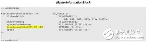
Various coupling ratio
Environment stable
Single mode and multimode available
High Reliability and Stability
High Channel counts
Wide wavelength range
Customized packaging and configuration
Applications:
FTTx Construction
Fiber CATV networks
Local area networks