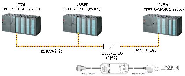
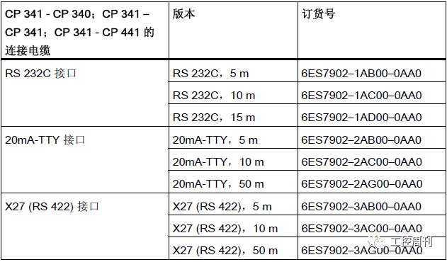
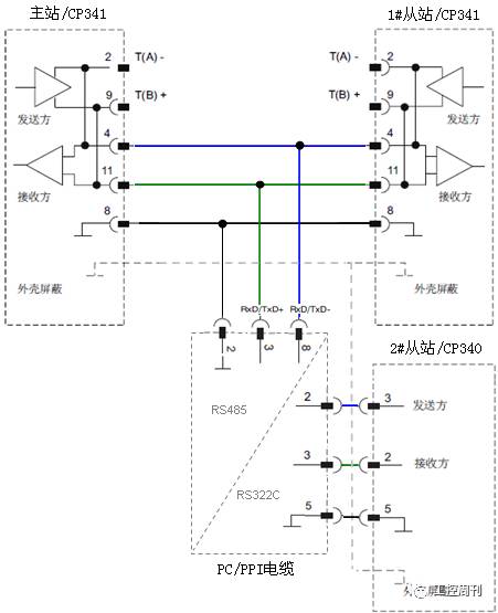
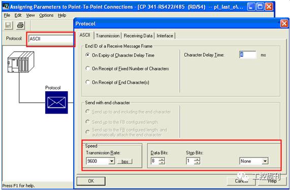
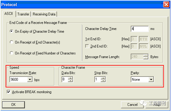
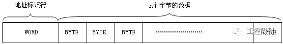
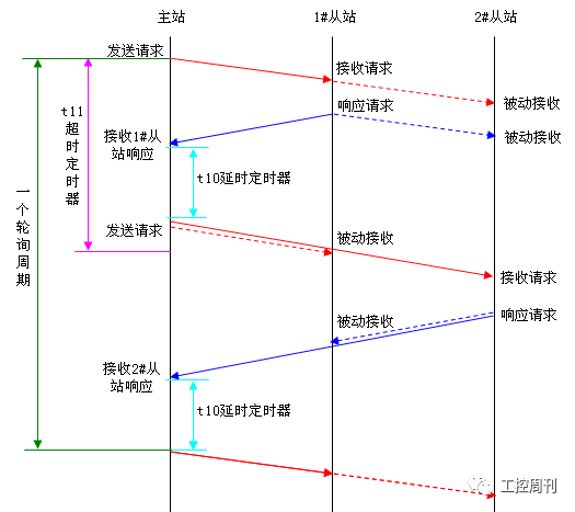
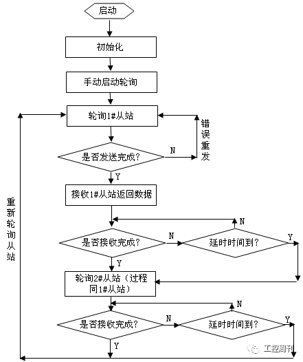
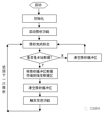
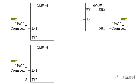
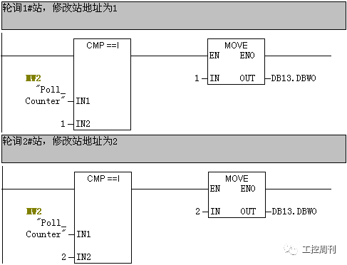
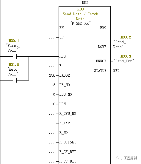
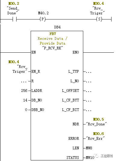
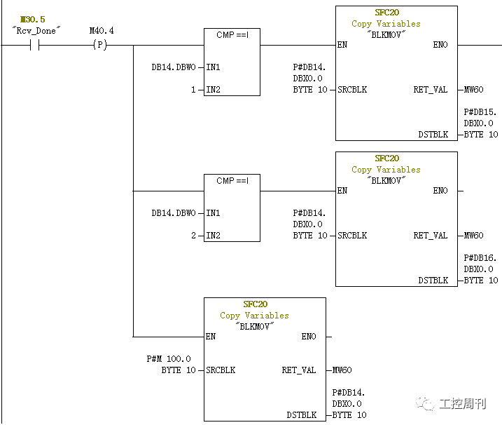
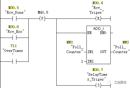
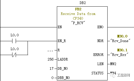
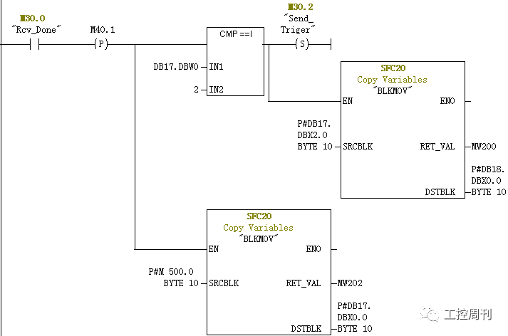
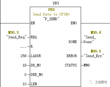
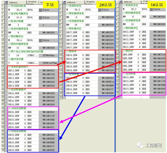
Siemens SIMATIC S7 series serial communication modules, including CP340, CP341, CP440-1, CP441-1/2, CPU313C/314C-2PtP and ET200S 1SI 3964/ASCII, all support ASCII driver protocol communication, can be widely used It performs point-to-point connection communication with instruments, devices and systems that support third-party ASCII protocols, and has the advantages of simple application, flexibility, and convenient use. This section provides a specific example of an application for polling communication between multiple Siemens serial communication modules (CP340/CP341) via the ASCII driver protocol. Its specific implementation method and polling principle have universal guiding significance, and can be used as a reference for serial communication between Siemens serial communication module and instruments, devices and systems supporting ASCII protocol. System composition As shown in the figure below, the system consists of three SIMATIC S7-300 stations, one of which acts as the master station for serial communication, polling the data of the other two slave stations via the ASCII driver protocol. The system master station and the 1# slave station are each configured with a serial communication module CP341 (6ES7341-1CH01-0AE0) (RS422/485 interface), and the 2# slave station is configured with a serial communication module CP340 (6ES7340-1AH02-0AE0). (RS232C interface), in order to connect them to a network, in this example, Siemens' PC/PPI cable (6ES7901-3CB30-0XA0) is selected to convert the RS232C interface of the 2# slave station to the RS485 interface to connect to the network. 2. Cable and hardware connection Detailed hardware connection as shown 3. Configuration master station Ø CP341 module start address 256 , ASCII protocol mode; Ø End of message frame standard: character delay time 4ms ; Ø Baud rate: 9600bps , 8 data bits, 1 stop bit, no parity; Ø Interface type: RS485 half duplex; Ø Others use default values. 4. Configuring the slave The parameter assignments for the slave CP341/CP340 modules are identical to those of the master station, paying particular attention to the baud rate, data bits, stop bits and parity settings to be the same as the master. 5. Polling principle Unlike MODBUS protocol polling, since each slave does not have unique device identification information (slave address), it cannot directly distinguish and identify which station of the data frame on the network is required, and which station needs to respond. Multi-site polling is implemented by ASCII protocol driver, and each station needs to be identified manually, and the corresponding instruction identifier is given when the primary station sends the polling instruction, so that the slave station can identify whether it is the data sent to itself or not. Whether to respond. In the process of implementing multi-site polling by ASCII protocol driver, the following aspects should be considered: Ø Basic mode: the master station actively requests, and the slave station responds according to the request; Ø Data frame: The information of the site identifier should be included in the sending or responding data frame; Ø Implementation method: timed polling, directly start the next job after completion, and delay the start of the next job after completion; Ø Verification, error handling mechanism: CRC , wait, discard, retry, etc. 6. Polling mechanism 1 data frame format In order to distinguish between the 1# slave station and the 2# slave station, an address identification character of one word is added to the message frame, and the primary station polls different slave stations by transmitting frames of different address identification characters, and the slave station judges whether according to the address characters. It is a message to yourself and is handled accordingly. The response frame sent by the slave station to the primary station also contains its own address identification character, which is used by the primary station to determine which slave station returns the data. The character frame format is as follows: 2 timing diagram 3 flow chart ☞Initialization process Initialization is primarily for the primary station. In the initialization phase, the CP module is parameterized, the polling counter is initialized, the receive buffer is reset, and the transmit data frame is generated according to the polling counter. ☞Main station polling process As shown in the figure below, after the system initialization is completed, the first polling operation is manually started. This example polls the 1# slave first. After sending a query request to the 1# slave station, wait for the response of the 1# slave station. If the data returned by the 1# slave station is received within the specified delay time, the query request is sent to the 2# slave station, and waits for 2#. The slave's response, if the data returned by the 2# slave is received within the specified delay time, a complete polling is completed and a new round of polling is automatically initiated. If the return data or reception error of the slave cannot be received within the specified delay time, skip the station and start polling the next station. ☞Slave response process The slave responds according to the request of the primary station, mainly after receiving the data on the network, and determining whether it is the data given to itself. If yes, the data is received into the designated data area, and the sending function is started, and the corresponding return data is sent to the primary station; if not, the received data is directly deleted without any response. 7. Master program 1 initialization In order to implement polling for multiple slaves, the program constructs a polling counter that modifies the station address identification character in the data frame sent by the primary station by modifying the value of the polling counter. Here, MW2 is defined as the polling counter. The program starts. The polling counter is operated first. By default, the 1# slave is polled and the value 1 is assigned to MW2. During the execution of the program, the value of the polling counter is modified, and the address identifier word of the transmitted data block is modified correspondingly by judging the value of the polling counter to complete the polling of the responding slave. The specific implementation here is as follows, in which DB13 is used as a transmission data block and DB13.DBW0 is an address identifier word. 2 start sending After the initialization is complete, the send function can be started. Here, the first transmission is performed manually, by triggering the manual start flag M30.1, and calling FB8 P_SND_RK to send data to the slave. After the first transmission is completed, the automatic polling flag M30.0 can be automatically modified by the program to realize the function of automatically transmitting data to the slave. After the transmission function block FB8 is started, the status information is returned via FB8 to determine whether the transmission is completed. If the transmission is incorrect, the transmission function is restarted. ☞ Send completed: Start the receiving job and prepare to receive the slave to return data. At the same time, a timeout timer T11 is started. If the timeout period expires and no data has been received, the device waits for a call and starts polling the next station. 3 Receive slave data return After the transmission is completed, the receiving job is started, the receiving slave data is ready to be received, and the received data is first placed in the receiving buffer, where the DB14 data block is the receiving buffer. 4 receiving completed After the reception is completed, the following aspects are handled. If you receive an error or timeout, skip polling for this station. ☞ the address data received from the data identifier is determined from which the station, and transfer data from the receive buffer to the specified slave data storage area while emptying the receive buffer; ☞Reset the receive flag and modify the value of the polling counter to prepare to poll the next slave; ☞Reset timeout timer; ☞ Start a delay timer and start polling the next slave after the delay time has elapsed. 8. Slave program The slave's handler is relatively simple relative to the master. Let's take the example of 2# slave station as an example. The 1# slave station is the same as the 2# slave station except that the FB is called differently. 1 receiving data The slave station always starts the receiving function FB2 P_RCV, receives data from the network, and if it receives the data, it determines whether it is the data of the station according to the address identifier: ☞ is the data of the station, the data in the receive buffer (DB17) is moved to the specified address area (DB18), and the receive buffer is cleared. At the same time, the sending flag is triggered, and the return data is sent to the primary station; ☞Not the data of this station, directly clear the receive buffer (DB17). 2 send return data After the reception is completed, the sending function is called to send the data of DB19 to the primary station. 9. Experimental results Set up the network, and download the program to their respective CPUs to start the CPU. The polling program can be started by setting the manual start polling flag M30.0. The variable table can be used to monitor the operation of the system. It can be seen that the primary station cyclically transmits data to two slaves, and also cyclically receives return data from the slaves, as shown in the following figure.
A Main Distribution Frame (MDF) is a signal distribution frame or cable rack used in telephony to interconnect and manage telecommunication wiring between itself and any number of intermediate distribution frames and cabling from the telephony network it supports.
What's more,we can also offer you the MDF Termination Block with good quality and low price.
MDF Patch Panel, Patch Panel Rack, Network Patch Panel NINGBO YULIANG TELECOM MUNICATIONS EQUIPMENT CO.,LTD. , https://www.yltelecom.com