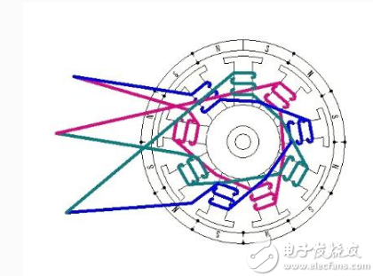
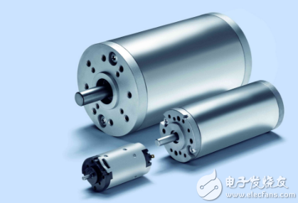
With the increasing popularity of electric vehicles and the fierce competition in the market, many companies and merchants have made advertisements in addition to the price and appearance of the products, and also advertised in the small details of electric vehicles. The most popular is the brushing and brushless promotion of the motor, and the advertising of the brushless motor is one of the highlights. When you see this noun, you can't help but think that if there is no brush, there must be a brush, so where is the difference between brush and brushless? The following small series will answer you for you. Definition of brush motor and brushless motor Brushless motor: The brushless DC motor is composed of a motor body and a driver, and is a typical mechatronic product. Since the brushless DC motor is operated in a self-controlled manner, the starting winding is not added to the rotor like the synchronous motor with heavy-load starting under the variable frequency speed regulation, and the oscillation and the out-of-step are not generated when the load is abrupt. The permanent magnets of the medium and small capacity brushless DC motors are now mostly made of high magnetic energy product rare earth neodymium iron boron (Nd-Fe-B) materials. Therefore, the volume of the rare earth permanent magnet brushless motor is reduced by one frame number compared with the same capacity three-phase asynchronous motor. The difference between the two
Product Features
1, built-in over-current overheating, temperature control circuit technology.
2, the module design, easy installation, online replacement.
3, low leakage current, fast response time, low residual voltage.
4, alarm indication device, green (normal) v red (fault).
Maximum Discharge
Current Imax(8/μ20μs)kA
Nominal Discharge
Current In(8/μ20μs)kA
Operating
Environment-C
Surge Protector SPD,Surge Protection Device SPD,SPD Wenzhou Korlen Electric Appliances Co., Ltd. , https://www.zjmoldedcasecircuitbreaker.com
Brushed motor: A brushed motor is a rotating electrical machine that contains a brush device that converts electrical energy into mechanical energy (electric motor) or converts mechanical energy into electrical energy (generator). The brush motor is the basis of all motors. It has the characteristics of quick start, timely braking, smooth speed regulation in a wide range, and relatively simple control circuit. 
1. When the brush motor is working, the coil and the commutator rotate, the magnetic steel and the carbon brush do not rotate, and the alternating change of the coil current direction is completed by the commutator and the brush that rotate the motor. In the electric vehicle industry, there are brush motor divided into high speed brush motor and low speed brush motor. There are many differences between brush motor and brushless motor. From the name, it can be seen that the brush motor has a carbon brush, and the brushless motor has no carbon brush.
2. The brushless DC motor is composed of a motor main body and a driver, and is a typical electromechanical integration product. Since the brushless DC motor is operated in a self-controlled manner, it does not add a start winding to the rotor like the synchronous motor that is restarted under variable frequency speed regulation, and does not cause oscillation and out-of-step when the load is abrupt.
3, brush motor is a traditional product, the performance is relatively stable.
Brushless motors are upgraded products that have better life performance than brushed motors. However, its control circuit is more complicated, and the aging screening requirements for components are more stringent. Although the motor has a long life, the control circuit is prone to problems. Therefore, brushless motors are subjected to rigorous reliability tests to ensure quality. However, with the continuous upgrading of technology, the brushless motor technology is quite mature.
4. In the actual production process, since the brushed toothed DC motor is a high-speed motor, the gear teeth are small and easy to wear, but the force is large and the climbing ability is strong. The brushless DC motor eliminates the trouble of replacing the carbon brush for two or three years in the process of use. However, due to the process of controlling the brushless motor, the accuracy is extremely high. Moreover, the price of the brushless motor controller is also higher. In contrast, there is a brushless toothless DC motor. Although it is necessary to replace the carbon brush, it is very easy to replace the carbon brush, and the motor control is relatively simple, the motor runs smoothly, and the safety factor is high.
5. Brushed motor means that the motor is a DC input. The controller that controls it can only adjust the speed by supplying the current. The brushless motor is actually a three-phase AC motor. The controller converts the DC power into three phases. AC power, and commutating according to the sensor Hall element in the motor to make the motor run normally. Directly speaking, a brushless motor has a longer life than a brushed motor, and it has a strong power to start, but the controller is more expensive than a brushed controller. At present, all of them are brushless controllers, and the brush has been basically eliminated. The electric vehicle controller is the core control device used to control the start, run, advance and retreat, speed, stop, and other electronic devices of the electric vehicle. It is like the brain of an electric vehicle and an important component of an electric vehicle.
Product Description
SPD Surge Protective Device,Lightning Surge Protector
Surge Protection Device (SPD)
It is a device used to limiting instant surge voltage and discharge surge current, it at least including a non-linear component.
Surge protective Device Model Selection
With the impact of international information flow, the rapid development of microelectronic science and technology, communication, computer and automatic control technology, make the building start to go for high quality, high functional area, formed a new building style-intelligent building. As inside the intelligent building there are lot of information system, <<Building lightning protection design norm>> GB50057-94(2002 vision)(hereafter brief as <<lightning protection norm>>) put forward the relative requirement to install the surge protective device, to ensure the information system safely and stable running.
SPD essentially is a equipotential connection material, its model selection is according to the different lightning protection area, different lightning electromagnetic pulse critical and different equipotential connection position, decide which kind of SPD used in the area, to achieve the equipotential connection with the common earth electrode. Our statement will based on SPD's maximum discharge current Imax, continuous operating voltage Uc, protection voltage Up, alarm mode etc.
As per << Lightning Protection Norm>> item 6.4.4 stipulation "SPD must can withstand the expected lightning current flow and should confirm to the additional two requirements: the maximum clamp voltage during surge across, capable to extinguish the power frequency follow-on current after lightning current across." That is the value of SPD's max. clamp voltage add its induction voltage of two ends should be same with the system's basic insulation level and the equipment allowed max. surge voltage.
SPD for Power Supply System Series Selection Guide
The installation of SPD at each lightning protection zone, according to the standard of low voltage electrical appearance, make classification of electrical equipment in accordance with the over voltage category, its insulation withstand impulse voltage level can determine the selection of SPD. According to the standard of low voltage electrical appearance, make classification of electrical equipment in accordance with the over voltage category as signal level, loading level, distribution and control level, power supply level. Its insulation withstand impulse voltage level are:1500V,2500V,4000V,6000V. As per to the protected equipment installation position different and the different lightning current of different lightning protection zone, to determine the installation position of SPD for power supply and the break-over capacity.
The installation distance between each level SPD should not more than 10m, the distance between SPD and protected equipment should as short as possible, not more than 10m. If due to limitation of installation position, can't guarantee the installation distance, then need to install decoupling component between each level SPD, make the after class SPD can be protected by the prior class SPD. In the low voltage power supply system, connecting an inductor can achieve the decoupling purpose.
SPD for power supply system specification selection principle
Max. continuous operating voltage: bigger than protected equipment, the system's max. continuous operating voltage.
TT System: Uc≥1.55Uo (Uo is low voltage system to null line voltage)
TN System: Uc≥1.15Uo
IT System: Uc≥1.15Uo(Uo is low voltage system to line voltage)
Voltage Protection Level: less than the insulation withstand impulse voltage of protected equipment
Rated discharge current: determined as per to the lightning situation of the position installed and lightning protection zone.
SP1 Series
Normal Working Conditions
-Altitude not exceed 2000m
-Ambient air temperature:
Normal range: -5ºC~+40ºC
Extend range: -40ºC~+80ºC
-Relative Humidity: 30% - 90% under indoor temperature condition
- At the place without obviously shaking and shock vibration
- Non-explosion danger medium, non-corrosion gas and dust ( including conductive dust)
Classification
-As per Nominal Discharge Current:
5,10,20,30,40,60KA(8/20µs)
- As per Maximum continuous operating voltage:
275V,320V,385V,420V,440V,460V
- As per to poles
1P,1P+N,2P,3P,3P+N,4P
- As per auxiliary functions:
a. With remote signal output ( remote alarm function)
b. Without remote signal output
Selection Principle
- The continuous applied voltage on the two terminals of SPD should not more than the maximum continuous operating voltage Uc value;
- The voltage protection level Up of SPD should less than the maximum impulse withstand voltage of the protected equipment;
- As per to the different earthing system and protection mode to select the specification accordingly;
Model/Technical Parameters
WR-B60
WR-B80
WR-B100
WR-B120
WR-B150
Rated Operating Voltage Un (V ~)
220V 380V
220V 380V
220V 380V
220V 380V
220V 380V
Maximum Continuous Operating Voltage Uc (V ~) kV
385V 420V
385V 420V
385V 420V
385V 420V
385V 420V
Voltage Protection Level Up (V ~) kV
≤1.8≤2.2
≤2.4≤2.5
≤2.5≤3.2
≤3.4≤3.7
≤4.0≤4.5
60
80
100
120
150
30
40
60
80
100
Response Time
<25
<100
L/N(mm²)The Cross Section Of L/N Line
16,25
16,25
16,25
16,25
25,35
PE (mm²)The Cross Section Of PE Line
16,25
25,35
25,35
25,35
35
Fuse or Switch (A)
63A
63A
63A,100A
63A,100A
63A,125A
The Line Section of Communication and Alarm (mm²)
≥ 1.5
(-40ºC~-+85ºC)
Relative humidity 25 ºC
≤95%
installation
Standard Rail35mm
Material of Outer Covering
Fiber Glass Reinforced Plastic